
 2026-10-14
 1
1. Introduction
The convergence of extreme power density and thermal management requirements in modern computing infrastructure has given rise to a new class of interconnect technology: the water cooling power connector. Unlike traditional power connectors, which are designed solely to transmit electrical energy, water cooling power connectors integrate fluid channels directly into the connector body, enabling simultaneous delivery of electrical power and cooling capacity to high-power components. This dual-function architecture represents a fundamental rethinking of the role of the power connector, transforming it from a passive electrical interface into an active participant in the thermal management system.
The emergence of water cooling power connectors is driven by the physical limits of air cooling. As processor and accelerator power ratings continue to escalate—with flagship GPUs now exceeding 700 W and data center racks approaching 100 kW or more—air cooling is no longer capable of removing the generated heat within practical constraints of airflow, acoustic noise, and energy consumption. Liquid cooling, with its superior heat transfer characteristics and ability to transport heat away from the source, has become the enabling technology for next-generation computing systems. Water cooling power connectors are the critical interface between the power delivery infrastructure and the liquid cooling loop, ensuring that both electrical and thermal requirements are met at the point of connection.
This analysis provides a comprehensive examination of water cooling power connectors, covering their technical principles, design requirements, material considerations, standards and specifications, applications in data centers and high-performance computing, and emerging trends. The discussion encompasses both dedicated liquid cooling connectors for fluid management and power connectors with integrated cooling features, reflecting the diversity of approaches to combined power and thermal management in modern computing systems.
2. The Thermal Challenge in High-Power Computing
2.1 Limits of Air Cooling
Air cooling, the dominant thermal management approach for computing systems since the earliest days of the industry, relies on the forced convection of air across a heat sink to remove heat from the processor or accelerator. The effectiveness of air cooling is governed by the heat transfer coefficient, which depends on the air velocity, the surface area of the heat sink, and the thermal conductivity of the materials. As power densities have increased, air cooling systems have had to grow larger, noisier, and more energy-intensive to maintain acceptable component temperatures. At the thermal design power (TDP) levels of modern high-end processors, air cooling is approaching fundamental physical limits: the air velocity required to remove the heat would exceed practical and acoustic constraints, and the heat sink would be too large to fit within standard form factors.
The practical upper limit of air cooling is generally considered to be around 300-400 W per component for conventional heat sink and fan configurations, though advanced designs with vapor chambers and high-performance fans can extend this range somewhat. For multi-GPU servers and high-density compute nodes, the aggregate heat load can reach several kilowatts per chassis, far beyond what air cooling can handle within the constraints of rack space and facility infrastructure. Liquid cooling becomes not merely an option but a necessity as power densities continue to rise.
2.2 Principles of Liquid Cooling
Liquid cooling systems transfer heat from the source to a remote heat exchanger using a liquid coolant, typically water or a water-glycol mixture. The advantages of liquid cooling over air cooling are substantial: the specific heat capacity of water is approximately 4.18 kJ/kg·K, more than four times that of air, and the thermal conductivity of water is approximately 0.6 W/m·K, roughly 25 times that of air. These properties allow liquid cooling systems to transport far more heat with a given flow rate and temperature difference, enabling more compact and efficient thermal management.
In a typical data center liquid cooling system, coolant is circulated through cold plates mounted on high-power components, absorbing heat through direct conduction. The warmed coolant is then transported to a coolant distribution unit (CDU), where it transfers its heat to a facility water loop or to an external heat rejection system. The cooled coolant is then recirculated to the cold plates, completing the loop. This architecture allows heat to be transported over significant distances with minimal temperature rise, decoupling the thermal load from the immediate vicinity of the computing hardware.
2.3 Implications for Connector Design
The adoption of liquid cooling has profound implications for connector design. Every connector that penetrates the liquid cooling boundary—whether for electrical power, data, or fluid—must maintain its functional integrity in the presence of coolant, elevated temperatures, and potentially elevated humidity. Connectors must be compatible with the coolant chemistry, resistant to corrosion and degradation, and designed to prevent leakage that could damage electronic components or create safety hazards.
The integration of liquid cooling with power delivery creates additional challenges. Power connectors that carry high currents generate heat at the contact interface, and this heat must be managed within the overall thermal budget of the system. In some designs, the power connector itself may be liquid-cooled, with coolant channels routed through the connector body to remove heat from the contacts. In other designs, the power connector may be positioned in close proximity to a cold plate, relying on conduction and convection for thermal management. The optimal approach depends on the current level, the connector size, and the overall system architecture.
3. Types of Water Cooling Power Connectors
3.1 Dedicated Liquid Cooling Connectors
Dedicated liquid cooling connectors, often referred to as quick disconnect couplings or fluid connectors, are designed to manage the flow of coolant between system components without carrying electrical power. These connectors are essential for the reliable operation of liquid cooling systems, providing leak-free connections that can be mated and unmated without spilling coolant or introducing air into the loop.
The Universal Quick Disconnect (UQD) series, developed in accordance with Open Compute Project (OCP) specifications, is the predominant standard for data center liquid cooling connectors. The UQD series features an automatic steel ball-lock mechanism that enables quick connect and disconnect, and is available in four standard OCP sizes (UQD02/04/06/08) as a standard push-pull socket. The connectors are designed for leak-free operation, with a bidirectional shut-off valve and dry break that prevent accidental spillage or drips during connection and disconnection.
The UQD Blind-Mate (UQDB) variant adds blind mating capability with a radial compensation of 1 mm, allowing the connector to automatically connect and seal when the server tray is inserted into the rack. This feature is particularly valuable in high-density data center environments, where manual connection of individual coolant lines would be impractical and error-prone. The UQDB connector simplifies installation and improves system reliability by eliminating the need for precise alignment during mating.
3.2 Power Connectors with Integrated Liquid Cooling
A second category of water cooling power connector integrates electrical power delivery and liquid cooling into a single connector body. These connectors are designed for applications where the power connector itself generates significant heat that must be removed to maintain reliable operation. By routing coolant through the connector body, the contact temperature can be maintained within safe limits even at very high current levels.
The electrical connector with cooling liquid circulation slot, described in recent patent literature, is an example of this approach. The connector incorporates a cooling liquid circulation slot within the housing, allowing coolant to flow directly past the current-carrying contacts and absorb the heat generated by electrical resistance. This design enables the connector to carry higher currents than would be possible with conventional air-cooled connectors of the same size, while maintaining contact temperatures within the rated limits of the materials.
Another approach, developed by Fujikura, is a power supply connector with a built-in cooling pipe that circulates fluid to transfer heat from the terminal to the outside of the housing. This design achieves high cooling efficiency with a simplified structure, making it suitable for applications where space is constrained and conventional cooling methods are not feasible.
3.3 Hybrid Approaches: Combined Power and Fluid Quick Disconnects
A third category of water cooling power connector combines the functions of a power connector and a fluid quick disconnect into a single integrated interface. These hybrid connectors allow a single mating action to establish both electrical power delivery and coolant circulation, simplifying installation and reducing the number of separate connections required.
Stäubli has developed integrated power and liquid cooling connectivity solutions compatible with OCP Open Rack v3 (ORv3) architectures, combining high-current power contacts with non-spill quick couplings in a single connector housing. This integration reduces the space required for connections, simplifies cable and hose routing, and reduces the risk of installation errors. The combined connector is particularly well-suited to blind-mate applications, where the server tray is inserted into the rack and all connections—power, data, and fluid—are established simultaneously.
4. Design Requirements and Technical Specifications
4.1 Electrical Performance
Water cooling power connectors must meet stringent electrical performance requirements, including low contact resistance, high current-carrying capacity, and adequate voltage rating. The contact resistance of the power path directly affects the heat generated within the connector, which in turn affects the cooling load that the liquid cooling system must handle. Low contact resistance is therefore essential for both electrical efficiency and thermal management.
The current-carrying capacity of a water cooling power connector depends on the cross-sectional area of the conductors, the contact resistance of the mating interface, and the effectiveness of the cooling. In liquid-cooled connectors, the current rating can be significantly higher than for comparable air-cooled connectors, because the coolant removes heat directly from the contact area, preventing the temperature from rising to levels that would degrade the contact materials or the housing. TE Connectivity's Liquid Cool Busbar solution, for example, uses high-purity copper alloys to deliver up to 750 kW of power within a single rack while limiting thermal buildup.
4.2 Fluid Dynamics
The fluid dynamic performance of water cooling connectors is characterized by the flow rate, pressure drop, and flow resistance. High flow rates are desirable for effective heat transfer, but they come at the cost of increased pressure drop, which requires more pump power and may necessitate larger diameter tubing. The connector design must therefore balance flow performance against pressure drop, achieving adequate cooling without imposing excessive hydraulic load on the system.
The Everis DC in-line connector, developed by Colder Products Company, illustrates the importance of fluid dynamic optimization. Its full-flow design contributes up to 90% less pressure drop compared to valved connectors of the same size, optimizing cooling efficiency in tight spaces and reducing the draw from pumps and coolant distribution units. This reduction in pressure drop translates directly into energy savings and improved system efficiency, as the pumps require less power to circulate the coolant.
4.3 Leak Prevention and Sealing
Leak prevention is arguably the most critical requirement for any liquid cooling connector. A coolant leak can cause corrosion of electronic components, short circuits, and potentially catastrophic system failure. Even a small drip, if it occurs repeatedly over time, can lead to significant damage. The sealing system of a water cooling connector must therefore provide a reliable, long-lasting barrier against coolant escape, even under conditions of thermal cycling, vibration, and repeated mating and unmating.
Amphenol's UQD and UQDB connectors use high-performance, aerospace-grade sealing materials and feature a bidirectional shut-off valve and dry break for advanced protection against accidental spillage or drips. The UQDB series features redundant multi-lobed seals that provide extra protection against leaks over an extended period of time. The shell and spring of the connectors are constructed of stainless steel, which impedes corrosion and increases component longevity. Stainless steel grade 304 is commonly used for its broad material compatibility and corrosion resistance.
The dry break feature is particularly important for serviceability. When the connector is disconnected, the shut-off valve closes automatically, sealing both halves of the connector and preventing coolant from escaping. This allows connectors to be mated and unmated without draining the cooling loop, simplifying maintenance and reducing downtime.
4.4 Material Compatibility
Water cooling connectors must be compatible with the coolant chemistry used in the system. Common coolants include deionized water, ethylene glycol, and propylene glycol, each with different chemical properties and material compatibility requirements. Deionized water, while an excellent coolant, is aggressive toward many metals and can leach ions from contact surfaces, leading to corrosion and degradation. Ethylene glycol and propylene glycol are less aggressive but have lower specific heat capacities than water, requiring higher flow rates to achieve the same cooling performance.
The materials used in water cooling connectors must be selected for compatibility with the specific coolant chemistry. Stainless steel 304 is widely used for connector bodies and springs due to its corrosion resistance and broad compatibility. Seal materials are typically EPDM or fluorocarbon elastomers, selected for their resistance to coolant degradation and their ability to maintain sealing performance over a wide temperature range. Plating materials such as nickel and gold are used on electrical contacts to provide corrosion resistance and stable contact resistance.
5. Standards and Specifications
5.1 Open Compute Project (OCP) Specifications
The Open Compute Project has played a central role in standardizing liquid cooling connectors for data center applications. The OCP UQD specification defines the mechanical dimensions, performance requirements, and test methods for universal quick disconnect couplings used in liquid cooling systems. The specification has evolved through several revisions, with Revision 2.0 representing the current state of the art.
The OCP UQD specification covers both handmate and blindmate versions of the connector, specifying nominal sizes UQD02, UQD04, UQD06, and UQD08 corresponding to different flow capacities. The specification defines the mating interface, locking mechanism, seal configuration, and performance requirements for flow rate, pressure drop, and leak rate. Compliance with the OCP specification ensures interoperability between connectors from different manufacturers, allowing data center operators to source components from multiple suppliers without sacrificing compatibility.
5.2 Industry Standards and Certifications
Beyond the OCP specification, water cooling connectors may be subject to a range of industry standards and certifications depending on their application and geographic market. These may include standards for electrical safety (such as UL and IEC), fluid compatibility (such as NSF for potable water applications), and environmental performance (such as IP ratings for ingress protection). In data center applications, connectors may also need to comply with the requirements of the relevant building codes and fire safety regulations.
For power connectors with integrated liquid cooling, additional standards may apply. The electrical portion of the connector must meet the applicable requirements for voltage rating, current rating, and insulation coordination, while the fluid portion must meet the requirements for leak-tightness, pressure rating, and material compatibility. The integration of electrical and fluid functions in a single connector may require testing beyond what is specified for either function individually, including tests for electrical leakage in the presence of coolant and for coolant leakage in the presence of electrical stress.
6. Applications in Data Centers and HPC
6.1 AI Data Centers
Artificial intelligence data centers are among the most demanding applications for water cooling power connectors. AI training clusters, equipped with hundreds or thousands of high-power GPUs, generate enormous quantities of heat that must be removed efficiently to maintain performance and reliability. Liquid cooling is increasingly the only viable thermal management approach for these systems, and water cooling connectors are essential components of the cooling infrastructure.
TE Connectivity's Liquid Cool Busbar solution is designed specifically for AI data center applications, delivering up to 750 kW of power within a single rack while managing thermal dissipation. The solution uses high-purity copper alloys for the busbar conductors, minimizing electrical resistance and heat generation, and incorporates liquid cooling channels that remove heat from the busbar and connectors. This integrated approach allows the power delivery system to operate at higher current densities than would be possible with air cooling, reducing the space required for power distribution and freeing up rack space for compute hardware.
The connectors used in these systems must meet stringent requirements for reliability, serviceability, and safety. The UQD series connectors, with their OCP-compliant design and leak-free operation, are widely used in AI data centers for connecting servers to coolant manifolds and CDUs. The blind-mate UQDB variant is particularly suited to high-density environments, where the ability to hot-swap server trays without manual fluid connections is a significant operational advantage.
6.2 High-Performance Computing (HPC)
High-performance computing systems, including supercomputers and large-scale scientific computing clusters, have been early adopters of liquid cooling. The extreme power densities of HPC systems—with compute nodes often exceeding 1 kW per node—make air cooling impractical, and liquid cooling has been the standard thermal management approach in this domain for many years.
Water cooling connectors in HPC applications must handle a wide range of flow rates and pressure requirements, from small-diameter lines serving individual processors to large-diameter manifolds distributing coolant to entire racks. The connectors must be compatible with the coolant chemistry used in the system, which may include corrosion inhibitors, biocides, and other additives to maintain coolant quality and system reliability. The ability to disconnect and reconnect connectors for maintenance without introducing air into the loop or spilling coolant is essential for operational efficiency.
6.3 GPU Server and Accelerator Cooling
The rapid increase in GPU power ratings has made liquid cooling increasingly common in GPU servers, even in configurations that would previously have been air-cooled. Flagship GPUs such as the NVIDIA RTX 5090, with a TDP exceeding 500 W, generate heat loads that are challenging to manage with air cooling alone, and liquid-cooled versions of these cards are available from multiple vendors.
The power connector on high-power GPUs is a significant thermal concern. The 12V-2x6 connector, which delivers up to 600 W to the GPU, can reach elevated temperatures under sustained load, and thermal management of the connector area is critical for reliability. Bitspower's water block for the RTX 5090 incorporates a backplate designed to cover the power connector and help dissipate heat, reflecting the recognition that connector thermal management is an integral part of GPU cooling system design.
In some advanced designs, the power connector itself may be liquid-cooled. This approach, while more complex, offers the most effective thermal management for the connector, allowing higher currents to be delivered without exceeding the temperature limits of the connector materials. As GPU power ratings continue to increase, the integration of liquid cooling with power delivery at the connector level is likely to become more common.
7. Emerging Trends and Future Directions
7.1 Higher Voltages and Power Levels
The trend toward higher voltages in data center power distribution—from 12 V to 48 V and potentially higher—will have significant implications for water cooling power connectors. Higher voltages reduce the current required to deliver a given power level, which reduces resistive losses and allows smaller conductors. However, higher voltages also increase the risk of electrical breakdown and require greater creepage and clearance distances, which may conflict with the compact form factors required for high-density data center applications.
Water cooling connectors designed for higher voltages will need improved insulation systems, with materials selected for high dielectric strength and resistance to tracking and erosion. The sealing systems must also be designed to prevent coolant from bridging the increased electrical clearances, which could create a leakage path and compromise safety. These requirements will drive innovation in connector design and materials, potentially leading to new connector architectures optimized for high-voltage liquid cooling applications.
7.2 Immersion Cooling Compatibility
Immersion cooling, in which electronic components are submerged in a dielectric coolant, is an alternative to cold plate liquid cooling that offers potentially higher cooling efficiency and simpler system architecture. However, immersion cooling imposes different requirements on connectors than cold plate cooling. Connectors used in immersion cooling must be compatible with the dielectric coolant, which may be a hydrocarbon-based fluid or a fluorochemical fluid with different material compatibility requirements than water.
The power connectors used in immersion-cooled systems must be resistant to the dielectric fluid and must maintain reliable electrical performance in the presence of the fluid. The P13/PA13 connector, widely used in immersion-cooled mining installations, has demonstrated compatibility with hydrocarbon-based coolants when specified with oil-resistant cable variants. As immersion cooling gains adoption in data centers, the demand for immersion-compatible power connectors is likely to grow.
7.3 Standardization and Interoperability
The continued growth of the liquid cooling ecosystem depends on standardization and interoperability between components from different manufacturers. The OCP UQD specification has been instrumental in establishing a common standard for liquid cooling connectors, and its adoption by multiple manufacturers has created a competitive market for OCP-compliant connectors.
Future standardization efforts are likely to extend beyond fluid connectors to encompass the integration of power and fluid connections. Standards for combined power-and-fluid connectors would enable the development of plug-and-play liquid cooling solutions that simplify deployment and reduce the risk of installation errors. The OCP community is already working on specifications for blind-mate connectors and combined power-and-fluid interfaces, and these efforts are expected to accelerate as liquid cooling becomes more widespread.
7.4 Smart Connectors and Monitoring
The integration of sensors and monitoring capabilities into water cooling power connectors is an emerging trend that promises to improve system reliability and operational efficiency. By incorporating temperature sensors, flow sensors, and contact resistance monitors into the connector, it becomes possible to continuously monitor the health of the connection and detect degradation before it leads to failure.
Smart connectors could also provide data for predictive maintenance, allowing operators to replace connectors before they fail and avoid unplanned downtime. The data collected by smart connectors could be integrated into data center management systems, providing a comprehensive view of power delivery and cooling system health across the entire facility. While smart connector technology is still in its early stages, it represents a promising direction for future development.
Water cooling power connectors represent a critical enabling technology for the next generation of high-performance computing infrastructure. As power densities continue to rise and air cooling reaches its physical limits, the integration of liquid cooling with power delivery becomes not merely an option but a necessity. The connectors that bridge the electrical and thermal domains must meet demanding requirements for electrical performance, fluid dynamics, leak prevention, and material compatibility, while also being reliable, serviceable, and cost-effective.
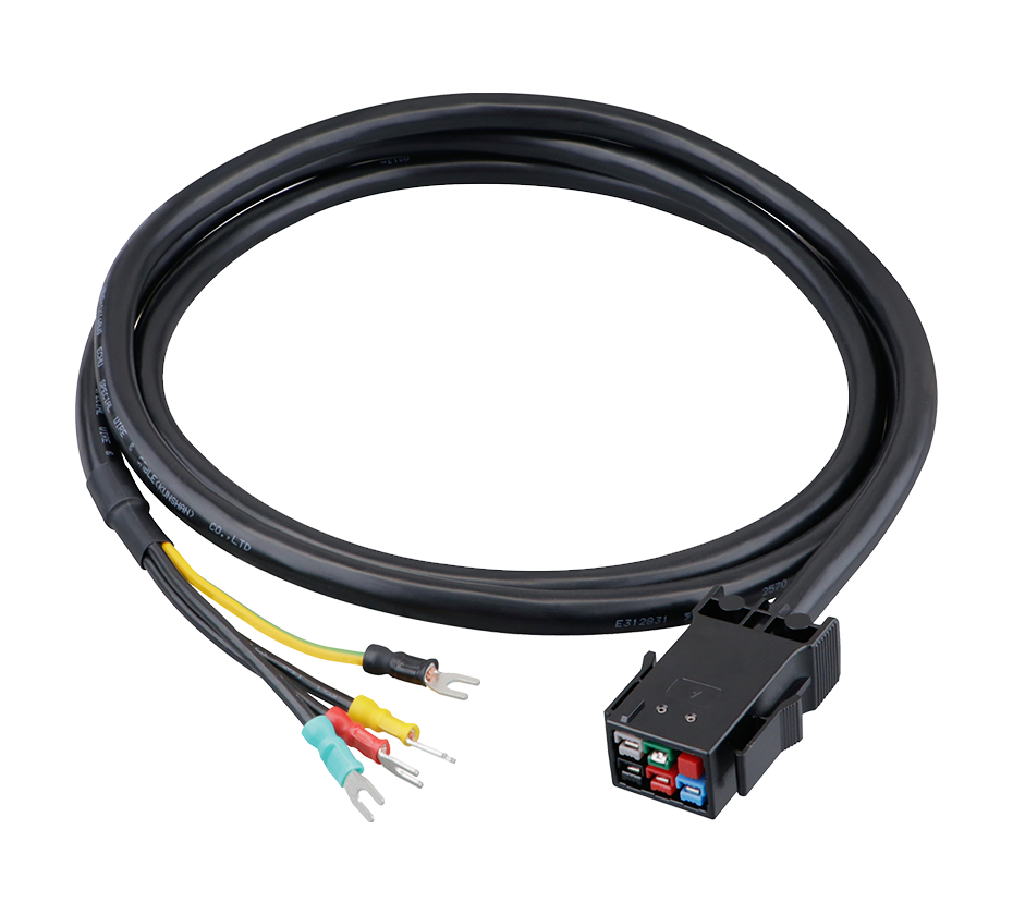
The P13 connector family, in its various forms, illustrates the diversity of approaches to power interconnection in modern computing systems. From the compact SATA power connector used within server chassis to the robust high-current connector used in mining and HPC applications, P13 connectors serve a wide range of power delivery needs. As the industry moves toward higher voltages, higher power densities, and more widespread adoption of liquid cooling, the P13 connector family and its successors will continue to evolve, driven by the relentless demands of artificial intelligence, high-performance computing, and data center infrastructure.
 Yang.taya@aitmpower.com
Tel: 15382891313
Phone: 0769-88878951
Fax: 0769-88878955
Wechat: 15382891313


 CN
 CN
 Home >


