
 2026-10-14
 1
1. Introduction
The P13 power connector occupies a distinctive and often misunderstood position in the landscape of modern electrical interconnect systems. Unlike standardized interface families such as USB or IEC 60320, the designation "P13" is not governed by a single universal specification. Instead, it refers to multiple distinct connector types across different application domains, ranging from internal server storage power delivery to high-current direct current (DC) connections for cryptocurrency mining hardware and high-performance computing infrastructure. This semantic ambiguity has significant practical implications for engineers, system integrators, and procurement specialists, as selecting the wrong "P13" connector can result in incompatible mating interfaces, inadequate current-carrying capacity, or catastrophic connection failure. Understanding the P13 connector family therefore requires a disaggregated approach that examines each variant within its specific technical and application context.
The importance of P13 connectors has grown considerably in recent years, driven by two parallel trends in computing infrastructure. First, the proliferation of high-density storage configurations in enterprise servers has placed greater demands on internal power distribution, where compact connectors must deliver multiple voltage rails to multiple drives within increasingly constrained chassis volumes. Second, the explosive growth of ASIC-based cryptocurrency mining and the emergence of high-power GPU servers for artificial intelligence workloads have created demand for rugged, high-current DC connectors capable of handling sustained loads of 45 A or more at elevated ambient temperatures. In both contexts, the P13 designation serves as a shorthand for a class of connectors optimized for specific power delivery requirements, and a thorough understanding of these requirements is essential for reliable system design.
This analysis provides a comprehensive examination of P13 power connectors across their major variants. It begins with a taxonomic overview that distinguishes the principal P13 connector types, followed by detailed technical specifications for each. Subsequent sections address application contexts, design and material considerations, installation and maintenance practices, comparative positioning against alternative connector families, and emerging trends that are likely to shape the future evolution of P13-class interconnects.
2. Defining the P13 Connector: A Taxonomy
2.1 Internal SATA Power Connector (Intel P13 Designation)
Within the context of Intel server chassis technical product specifications, the P13 designation refers to a specific five-pin SATA power connector used for internal peripheral power distribution. This connector is documented in Intel's technical product specifications for entry-level server chassis, where it is identified as a "SATA Power Connector (P13)" with a defined pinout and connector housing specification. The connector housing is specified as JWT A3811H00-5P or equivalent, with contacts designated as JWT A3811TOP-0D or equivalent. This five-pin configuration delivers three voltage rails—+3.3 V, +5 V DC, and +12 V—along with two common return paths, using 18 AWG wire for each conductor.
The Intel P13 SATA power connector is designed for internal use within server chassis, providing power to 2.5-inch storage drives and other low-power peripherals. Its current-carrying capacity is modest by modern standards, reflecting the relatively low power requirements of traditional SATA storage devices. The connector's significance lies primarily in its role as a standardized internal power interface within Intel's server platform ecosystem, where consistent pinout and mechanical dimensions facilitate chassis-level integration and field serviceability.
2.2 High-Current DC Connector (P13/PA13 for Mining and HPC)
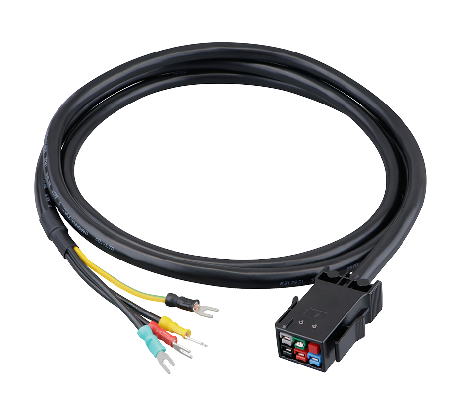
In a completely different technical context, the P13 designation—often used interchangeably with PA13 or PA45—refers to a four-pin high-current DC connector developed for the cryptocurrency mining industry and subsequently adopted in high-performance computing and GPU server applications. This connector is rated for 45 A at 600 V, making it suitable for single-phase 220 V/277 V power distribution in mining farms and data center environments. The P13/PA13 connector is characterized by silver-plated copper terminals, a locking mechanism to prevent accidental disconnection, and a color-coded grounding design that facilitates safe installation and maintenance.
The P13/PA13 four-pin connector was introduced by Bitmain with the S21 and S19j XP generation of Antminer equipment, replacing the older C13/C14 connectors used on previous generations of mining hardware. This transition reflected the increasing power demands of next-generation ASIC miners, which required a more robust and higher-current connector than the standard IEC 60320 interface could provide. The connector mates with a corresponding P14/PA14 female socket on the APW17 power supply unit, forming a secure and low-resistance power path for the hashboards.
The four-pin configuration of the P13/PA13 connector is a deliberate design choice that balances current-carrying capacity against connector size and mating force. By distributing the load across four pins, the connector achieves the required ampacity without relying on a single large contact, which would be more difficult to mate and more susceptible to thermal degradation. The pins are spaced to provide adequate creepage distance, reducing the risk of electrical breakdown under high-voltage operation.
2.3 Distinguishing the Variants
The coexistence of these two P13 connector types under a single designation creates a significant potential for confusion. The internal SATA P13 connector is a five-pin, low-current interface used within server chassis for storage power delivery, while the high-current P13/PA13 connector is a four-pin, high-power interface used for mining and HPC power distribution. They are not interchangeable, and neither is compatible with the other's mating interface. Engineers and technicians must therefore exercise care to specify the correct P13 variant for each application, paying particular attention to pin count, current rating, and intended use case.
3. Technical Specifications
3.1 Intel P13 SATA Power Connector
The Intel P13 SATA power connector is defined by a specific pinout that provides three positive voltage rails and two return paths. Pin 1 carries +3.3 V and is typically color-coded orange in standard wiring conventions. Pins 2 and 4 are common return (COM) connections, color-coded black. Pin 3 carries +5 V DC and is color-coded red. Pin 5 carries +12 V and is color-coded green. This pinout matches the standard SATA power connector specification, ensuring compatibility with SATA storage devices across a wide range of manufacturers.
The connector housing is specified as JWT A3811H00-5P or equivalent, a five-position nylon housing designed for wire-to-board or wire-to-wire applications within server chassis. The contacts are JWT A3811TOP-0D or equivalent, crimp-style terminals designed for 18 AWG wire. The 18 AWG wire gauge is appropriate for the current levels typical of SATA storage devices, which generally draw less than 1 A per voltage rail during normal operation, with transient peaks that are well within the connector's thermal capacity.
The P13 SATA power connector's current rating is not typically specified as a standalone figure in Intel documentation, as it is intended for use within the overall power budget of the server chassis. However, the 18 AWG wire and the contact design imply a practical continuous current capacity of approximately 3-5 A per pin, which is more than sufficient for 2.5-inch SATA drives and other low-power peripherals. The connector's voltage rating is compatible with the 12 V, 5 V, and 3.3 V rails it is designed to carry, with appropriate insulation and creepage distances to prevent arcing or short circuits.
3.2 High-Current P13/PA13 Connector
The high-current P13/PA13 connector is specified for significantly higher electrical loads than its SATA namesake. The connector is rated for 45 A at 600 V, a rating that reflects its intended use in single-phase 220 V/277 V power distribution systems. The four-pin configuration distributes the total current across multiple contact points, reducing the current per pin to approximately 11.25 A at the rated maximum, which is well within the capability of the silver-plated copper terminals.
The connector's voltage rating of 600 V provides substantial margin above the 277 V single-phase operating voltage, ensuring safe operation even under transient overvoltage conditions. The 45 A current rating supports a maximum power delivery of approximately 12.5 kW at 277 V, far exceeding the requirements of even the most power-hungry ASIC miners. This generous headroom reflects the connector's design philosophy: to provide a robust, reliable interface that can accommodate future increases in power demand without requiring a connector change.
The P13/PA13 connector employs silver-plated copper terminals for the contact interface. Silver plating offers several advantages over alternative finishes, including lower contact resistance, higher thermal conductivity, and superior resistance to oxidation and corrosion. These properties are particularly important in high-current applications, where even small increases in contact resistance can lead to significant localized heating and eventual connector failure. The connector housing is typically constructed from a high-temperature thermoplastic material that maintains its mechanical properties under sustained thermal load, and the locking mechanism ensures that the connector remains fully seated even in the presence of vibration or accidental contact.
3.3 Cable Specifications and Assemblies
P13/PA13 power cables are typically constructed using UL SJT 12 AWG wire for the current-carrying conductors, with a three-conductor configuration for single-phase applications. The 12 AWG wire gauge provides a balance between current capacity and flexibility, offering a current rating of approximately 20-25 A per conductor in typical installation conditions. For a four-pin connector carrying 45 A total, the use of 12 AWG wire ensures that voltage drop along the cable length is minimized and that the cable itself does not become a significant source of heat generation.
Cable assemblies are available in a range of configurations to suit different installation requirements. Common variants include C20-to-P13 cords for connecting miners to power distribution units (PDUs), P13-to-P13 cords for daisy-chaining or extending connections, and P13-to-P33 cords for connecting mining hardware to higher-capacity power sources. The C20 connector, rated for up to 16 A at 250 V, is the industry-standard IEC 60320 interface used on PDU outlets, while the P13 connector provides the high-current interface required by modern mining equipment.
For immersion-cooled mining installations, oil-resistant cable variants are available to withstand prolonged exposure to dielectric coolant fluids. These cables use specialized insulation materials that resist degradation from hydrocarbon-based coolants, ensuring long-term reliability in immersion cooling environments. The availability of application-specific cable variants reflects the maturation of the P13 connector ecosystem and the recognition that different cooling and power distribution architectures impose different requirements on interconnect components.
4. Applications and Use Cases
4.1 Enterprise Server Storage Power
The Intel P13 SATA power connector is used within server chassis to provide power to 2.5-inch SATA storage drives. In a typical server configuration, a single P13 connector may power one or more drives through a daisy-chained cable assembly, with the connector's three voltage rails providing the 12 V, 5 V, and 3.3 V supplies required by SATA drives. The connector's compact form factor allows it to be routed within the tight confines of a server chassis, while the standardized pinout ensures compatibility with drives from multiple manufacturers.
The reliability requirements for server storage power connectors are stringent, as a power interruption can result in data loss or corruption. The P13 SATA connector's crimp-style contacts and positive retention features are designed to maintain a stable electrical connection over the service life of the server, even in the presence of thermal cycling and vibration. The use of 18 AWG wire provides adequate current capacity with a margin of safety, while the connector housing material is selected for flame retardancy and thermal stability.
4.2 Cryptocurrency Mining Power Distribution
The high-current P13/PA13 connector is the predominant power interface for modern ASIC-based cryptocurrency mining equipment. Bitmain's S21 and S19j XP miners, among the most widely deployed SHA-256 mining platforms, use a P14 socket on the APW17 power supply that mates with a P13 plug on the power cord. The connector's 45 A/600 V rating provides ample capacity for the miners' power requirements, which can exceed 3 kW per unit for the most powerful models.
In a mining farm environment, P13 connectors are used in both air-cooled and immersion-cooled configurations. Air-cooled installations typically use standard C20-to-P13 power cords to connect miners to PDUs, while immersion-cooled installations require oil-resistant cable variants that can withstand direct contact with dielectric coolant. The locking mechanism of the P13 connector is particularly important in mining applications, where vibration from cooling fans and pumps can cause non-locking connectors to work loose over time, leading to arcing and potential fire hazards.
4.3 High-Performance Computing and GPU Servers
Beyond cryptocurrency mining, the P13/PA13 connector has found application in high-performance computing and GPU server environments. The connector's high current rating and robust construction make it suitable for powering GPU accelerator cards and other high-power components in AI and machine learning clusters. Manufacturers such as ANEN have positioned P13 series connectors as suitable for "mining farms, GPU servers, and power distribution systems," reflecting the connector's versatility beyond its original mining application.
The adoption of P13 connectors in HPC environments is driven by the same factors that made them successful in mining: high current capacity in a compact form factor, robust locking mechanism, and compatibility with industry-standard power distribution infrastructure. As GPU power requirements continue to increase—with flagship accelerators now exceeding 700 W per card—the need for reliable high-current connectors becomes ever more critical, and the P13/PA13 connector is well-positioned to meet this demand.
5. Design and Material Considerations
5.1 Contact Materials and Plating
The electrical performance and long-term reliability of P13 connectors depend critically on the materials and finishes used for the contact interface. The high-current P13/PA13 connector employs silver-plated copper terminals, a choice that reflects the demanding requirements of high-current DC power delivery. Silver offers the highest electrical conductivity of any metal, with a bulk resistivity of approximately 1.59 × 10⁻⁸ Ω·m at 20°C, marginally better than copper. More importantly, silver plating provides a stable, low-resistance contact interface that resists the formation of insulating oxide layers, which can cause contact resistance to increase over time and lead to thermal runaway in high-current applications.
The contact geometry of the P13/PA13 connector is designed to maximize the real contact area between mating terminals while minimizing insertion force. The four-pin configuration distributes the total current across multiple contact points, reducing the current density at each individual contact interface and lowering the risk of localized overheating. The contact surfaces are typically smooth and free of defects, ensuring that the contact resistance remains stable over many mating cycles.
For the Intel P13 SATA connector, the contacts are typically made from brass or phosphor bronze with a tin or gold plating. Tin plating is common for cost-sensitive applications where the connector is mated once and remains in place for the service life of the equipment, while gold plating is used in applications where multiple mating cycles are expected or where contact reliability is paramount. The contact design incorporates a spring element that maintains contact pressure over time, compensating for any relaxation of the housing material or wear of the contact surfaces.
5.2 Housing Materials
The connector housing serves multiple functions: it provides mechanical support for the contacts, ensures proper alignment during mating, maintains the required creepage and clearance distances for electrical safety, and protects the contacts from environmental contaminants. The housing material must therefore possess a combination of mechanical strength, thermal stability, electrical insulation properties, and flame retardancy.
High-current P13/PA13 connectors typically use glass-filled nylon or polybutylene terephthalate (PBT) for the housing, materials that offer high mechanical strength, excellent thermal stability (with continuous use temperatures exceeding 120°C), and UL 94 V-0 flame retardancy. The glass fiber reinforcement provides dimensional stability and resistance to creep under sustained load, ensuring that the connector maintains its mechanical integrity over the service life of the equipment. The housing design incorporates features such as polarizing keys to prevent incorrect mating, locking tabs to secure the connection, and strain relief provisions to protect the cable termination.
The Intel P13 SATA connector uses a similar class of housing materials, selected for compatibility with the internal environment of a server chassis. The housing is designed to be compact and low-profile, minimizing the space required for power distribution within the chassis. The connector's retention features are designed to withstand the vibration and thermal cycling typical of server operation without becoming dislodged.
5.3 Thermal Management
Thermal management is a critical consideration in the design of high-current power connectors. The P13/PA13 connector's 45 A rating implies significant heat generation at the contact interface, even with low contact resistance. The connector's thermal design must ensure that this heat is dissipated effectively to prevent the contact temperature from exceeding the material's rated limits.
Several design features contribute to the P13/PA13 connector's thermal performance. The silver plating on the contacts provides a low-resistance interface that minimizes Joule heating at the contact points. The copper terminals have high thermal conductivity, allowing heat to be conducted away from the contact interface and distributed throughout the terminal body. The connector housing, while not a primary heat dissipation path, provides some thermal mass that helps to buffer transient thermal loads. In high-power applications, the connector may be mounted to a heat sink or positioned in an airflow path to enhance convective cooling.
The cable itself also plays a role in thermal management. The 12 AWG wire used in P13/PA13 cable assemblies has a relatively large cross-sectional area, which reduces the current density within the conductor and minimizes resistive heating along the cable length. The wire insulation is selected for high-temperature operation, ensuring that the cable can withstand the heat generated by the connector without degrading or becoming brittle.
6. Installation, Maintenance, and Reliability
6.1 Termination Practices
Proper termination of P13 connectors is essential for reliable electrical performance and long-term safety. For the high-current P13/PA13 connector, the contacts are typically crimp-and-solder type, requiring both a mechanical crimp and a solder joint to secure the wire to the terminal. The crimp provides the primary mechanical retention and electrical connection, while the solder joint ensures a gas-tight, low-resistance interface that is resistant to corrosion and thermal fatigue.
The quality of the crimp termination has a significant impact on connector performance. An under-compressed crimp creates a high-resistance joint that generates excessive heat under load, potentially leading to connector failure. The use of the correct crimping die and tooling is therefore critical, as is the proper stripping of the wire insulation to the length specified by the connector manufacturer—typically 6-8 mm for the P13/PA13 connector. After crimping, the contacts are inserted into the connector body in the correct sequence and pushed until they snap into their locking position. Continuity and pin orientation should be verified before the connector is mated to the power supply.
6.2 Mating and Locking
The P13/PA13 connector features a locking mechanism that secures the plug to the receptacle, preventing accidental disconnection. The locking mechanism is designed to provide a tactile and audible click when the connector is fully seated, giving the installer positive confirmation of proper mating. The locking feature is particularly important in mining and HPC applications, where vibration from cooling fans, pumps, and other mechanical components can cause non-locking connectors to work loose over time.
Disconnection of the P13/PA13 connector requires actuation of the locking mechanism, which is designed to prevent accidental release while allowing deliberate disconnection when required. The connector should never be disconnected under load, as arcing at the contact interface can damage the contacts and create a fire hazard. In applications where hot-swapping is required, alternative connector types with hot-swap capability should be specified.
6.3 Failure Modes and Prevention
The most common failure mode for high-current P13 connectors is thermal degradation caused by elevated contact resistance. This can result from improper termination, contamination of the contact surfaces, or mechanical damage to the contacts. The symptoms of thermal degradation include discoloration of the connector housing, melting or deformation of the plastic, and in severe cases, arcing and fire. Regular inspection of P13 connectors in high-current applications is therefore recommended, with particular attention to any signs of overheating or discoloration.
Preventive measures include using only OEM-spec or equivalent connectors, ensuring proper termination with correct tooling, maintaining clean contact surfaces, and avoiding repeated mating and unmating cycles that can wear the contact surfaces. In high-reliability applications, contact resistance measurements can be used to monitor connector health and identify degradation before it leads to failure. The use of thermal imaging during routine maintenance can also help to identify connectors that are operating at elevated temperatures, providing an early warning of developing problems.
7. Comparative Analysis with Alternative Connector Families
7.1 P13/PA13 vs. IEC 60320 C13/C14
The transition from IEC 60320 C13/C14 connectors to P13/PA13 connectors in the mining industry reflects the limitations of the older interface for high-current applications. The C13/C14 connector is rated for 10 A at 250 V (or 15 A in some variants), which is insufficient for modern mining hardware that may draw 3 kW or more per unit. At 240 V, a 3 kW load requires approximately 12.5 A, exceeding the C13/C14 rating and creating a risk of overheating and fire. The P13/PA13 connector's 45 A rating provides substantial headroom, ensuring safe operation even under worst-case conditions.
Beyond current rating, the P13/PA13 connector offers a more robust locking mechanism, higher-quality contact materials, and a more compact form factor than the C13/C14 interface. The C13/C14 connector was designed for office equipment and consumer electronics, not for the demanding conditions of a mining farm or data center. The P13/PA13 connector, by contrast, was purpose-engineered for high-current DC power delivery in harsh environments.
7.2 P13 SATA vs. Molex and Other Internal Power Connectors
Within the server chassis, the Intel P13 SATA power connector competes with Molex-style connectors and other internal power interfaces. The Molex connector family, particularly the Mini-Fit Jr. series, offers higher current ratings and more robust construction than the SATA power connector, but at the cost of larger size and higher mating force. For low-power storage devices, the SATA power connector's compact size and standardized pinout make it the preferred choice, while Molex connectors are used for higher-power internal components such as fans and expansion cards.
The choice between SATA power and Molex connectors is typically dictated by the device being powered. SATA drives have standardized SATA power receptacles, while other internal components may use Molex or proprietary interfaces. The P13 designation in Intel documentation simply identifies the specific SATA power connector used in that chassis, and it is not intended to compete with Molex connectors in the broader market.
8. Future Trends and Developments
The future evolution of P13 connectors will be shaped by several converging trends in computing infrastructure. The continued growth of artificial intelligence and high-performance computing is driving demand for ever-higher power densities at the rack and node level, placing greater demands on power connectors. The shift toward liquid cooling, discussed in detail in the following section, is creating new requirements for connector thermal management and material compatibility. And the increasing emphasis on energy efficiency and sustainability is driving innovation in contact materials and connector designs that minimize power losses.
For the high-current P13/PA13 connector, the most significant trend is the migration toward higher voltages. The 48 V DC power distribution architecture, already adopted in some data center and telecommunications applications, offers significant efficiency advantages over traditional 12 V distribution, but it requires connectors with higher voltage ratings and improved creepage and clearance distances. The P13/PA13 connector's 600 V rating provides ample margin for 48 V operation, positioning it well for this transition. However, the connector may need to evolve in terms of contact materials, housing materials, and sealing to meet the more stringent requirements of 48 V systems.
For the Intel P13 SATA connector, the long-term trend is toward higher storage densities and the adoption of new storage interfaces such as NVMe over PCIe. While SATA remains widely deployed, its share of the storage market is gradually declining as NVMe drives become more cost-competitive. The P13 SATA power connector will therefore see declining volumes over time, though it will remain in service for many years in existing installations. The connector's design principles—compact size, standardized pinout, reliable contact system—will continue to inform the development of next-generation internal power connectors.
 Yang.taya@aitmpower.com
Tel: 15382891313
Phone: 0769-88878951
Fax: 0769-88878955
Wechat: 15382891313


 CN
 CN
 Home >


