
 2026-10-14
 4
The deployment of 5G networks represents one of the most significant transformations in telecommunications infrastructure since the advent of cellular technology itself. At the heart of this transformation lies an often-overlooked yet critically important component class: power supply system connectors. These electromechanical interfaces serve as the vital conduits through which electrical energy flows from power sources to the active electronic components that enable 5G communication—from massive MIMO antenna arrays to distributed baseband units. The unprecedented performance requirements of 5G—including higher power densities, elevated operating temperatures, and exposure to harsh outdoor environments—have driven substantial innovation in connector materials, architectures, and qualification standards.
This comprehensive analysis examines the technical landscape of 5G power supply system connectors, exploring the material science underpinning their construction, the architectural designs that enable reliable high-current transmission, and the qualification frameworks that ensure long-term field reliability. Particular attention is devoted to the copper alloy systems that form the conductive backbone of these connectors, the flame-retardant thermoplastic materials that provide insulation and structural integrity, and the evolving industry standards that govern their performance in mission-critical telecom applications.
1. Introduction: The Critical Role of Power Connectors in 5G Infrastructure
1.1 The 5G Power Challenge
The transition from 4G LTE to 5G New Radio (NR) technology has introduced a paradigm shift in the power delivery requirements of cellular base stations. Where a typical 4G macro base station might consume 1-2 kilowatts of power, a comparable 5G installation—particularly those deploying massive MIMO technology with 64 or 256 antenna elements—may demand 3-5 kilowatts or more per radio unit. This escalation in power demand, combined with the industry-wide push toward smaller form factors, natural convection cooling (eliminating forced-air or liquid cooling in many deployments), and operation in uncontrolled outdoor environments, has placed extraordinary demands on every component in the power delivery chain.
Power connectors occupy a unique position in this chain. Unlike active electronic components that can be protected within environmentally sealed enclosures, connectors must interface between the protected internal environment and the exposed external world. They must conduct substantial currents with minimal resistive losses, maintain reliable electrical contact across thousands of mating cycles and decades of service, resist corrosion and environmental degradation, and—critically—provide fire safety through the use of flame-retardant materials that do not compromise electrical or mechanical performance.
1.2 Scope and Organization
This analysis is organized into eight principal sections. Following this introduction, Section 2 examines the copper alloy systems that serve as the conductive elements in 5G power connectors, with particular focus on the Cu-Cr-Zr alloy family that has emerged as a preferred material for high-current applications. Section 3 explores the dielectric and structural materials—primarily glass-filled thermoplastics and modified polyphenylene ether blends—that provide insulation, mechanical support, and flame retardance. Section 4 addresses the architectural designs of both circular and board-to-board connector configurations optimized for 5G power delivery. Section 5 examines the environmental and electrical performance requirements, including IP ratings, current ratings, and EMI shielding. Section 6 provides a detailed treatment of flame-retardant standards and testing methodologies. Section 7 discusses industry qualification frameworks and standards compliance. Section 8 concludes with an assessment of future trends and emerging requirements.
2. Conductive Materials: The Copper Alloy Foundation
2.1 The Conductivity-Strength Trade-off
The fundamental challenge in designing conductive elements for power connectors lies in reconciling two inherently conflicting material properties: electrical conductivity and mechanical strength. Pure copper, the benchmark for electrical conductivity among engineering metals (second only to silver), possesses a conductivity of approximately 100% IACS (International Annealed Copper Standard) but exhibits a tensile strength of only about 230 MPa in its annealed state. This combination—high conductivity but low strength—renders pure copper unsuitable for connector contacts that must maintain reliable contact force over thousands of mating cycles and resist deformation under thermal and mechanical stress.
Conversely, alloying elements that enhance strength typically degrade conductivity by introducing electron scattering centers into the copper lattice. The connector designer’s task is therefore to identify alloy systems and processing routes that achieve the optimal balance for a given application—generally targeting conductivity values in the range of 70-85% IACS while achieving tensile strengths of 500-600 MPa or greater.
2.2 The Cu-Cr-Zr System for 5G Base Station Connectors
Among the various high-strength, high-conductivity copper alloy systems—including Cu-Fe-P, Cu-Ni-Sn, and Cu-Cr-Zr—the copper-chromium-zirconium system has emerged as particularly well-suited for 5G base station power connector applications. A recent patent (CN113943874B) describes a Cu-Cr-Zr alloy specifically developed for this purpose, with a composition comprising 0.80-1.30 wt% Cr, 0.10-0.25 wt% Zr, 0.05-0.15 wt% Si, and 0.01-0.05 wt% V, with the balance being copper.
The rationale for this specific composition is instructive. Chromium provides precipitation hardening through the formation of fine Cr-rich precipitates during aging treatment. Zirconium contributes to both precipitation hardening (as Cu₃Zr precipitates) and grain refinement, while also improving resistance to softening at elevated temperatures. The Si and V additions serve to further refine the precipitate structure and enhance thermal stability. The patent specifies that the combined Cr+Zr content should be 1.00-1.55 wt%, while the combined Si+V content should be 0.06-0.18 wt%, ensuring an optimal balance between precipitation strengthening and solid-solution effects on conductivity.
The performance targets for this alloy reflect the demanding requirements of 5G base station power connectors: high conductivity to minimize resistive heating under high current loads, high strength and hardness to provide reliable contact maintenance force, and high resistance to softening to withstand the elevated operating temperatures characteristic of 5G radio units where natural convection cooling may result in internal temperatures exceeding 85°C.
2.3 Comparative Analysis of Alternative Alloy Systems
Understanding why the Cu-Cr-Zr system is preferred over alternatives requires examining the performance limitations of competing alloys. The Cu-Fe-P system, while offering good conductivity (approximately 65% IACS or higher), achieves tensile strengths of only about 500 MPa in the alloy described in Chinese patent 202010199551.0. The Cu-Ni-Sn system, a spinodal decomposition-strengthened alloy, can achieve high hardness and strength (480-700 MPa tensile strength) but suffers from severely limited conductivity—typically only 10-12% IACS—rendering it unsuitable for high-current applications where resistive losses must be minimized.
Even within the Cu-Cr-Zr system, achieving the optimal combination of properties requires careful compositional control. Prior art alloys in this system, as described in the literature, have achieved conductivity of approximately 82.5% IACS with tensile strength of only 550 MPa. The alloy described in the ‘874 patent addresses this limitation through the specific Si and V additions that refine the precipitate structure, enabling higher strength without sacrificing conductivity.
2.4 Contact Plating Systems
While the bulk copper alloy provides the mechanical and basic electrical properties of the contact, the contact interface—where two connector halves mate—requires additional treatment to ensure reliable, low-resistance electrical connection over the connector’s service life. Contact plating serves multiple functions: preventing oxidation and corrosion of the base metal, providing a stable contact resistance, and reducing wear during mating cycles.
Gold plating is widely employed in telecom connector contacts. The Amphe-TVS connector from Amphenol Industrial Operations, designed specifically for base station power applications, utilizes gold-over-nickel plating on copper contacts. The nickel underlayer serves as a diffusion barrier, preventing copper from migrating through the gold layer and oxidizing at the surface, while the gold provides a noble, corrosion-resistant contact interface. For high-current applications, gold plating thickness in the range of 1.27 micrometers (50 microinches) is typical, as specified in the TE Connectivity 1479795-1 datasheet and the LEOCO 7621-0808GS specification.
The choice of contact material and plating must also consider the specific environmental exposure. For outdoor base station connectors, salt spray testing (500 hours with appropriate plating and base material) is a common qualification requirement, as specified for the Amphe-TVS connector.
3. Dielectric and Structural Materials: Flame-Retardant Thermoplastics
3.1 The Flame Retardance Imperative
Flammability performance is a non-negotiable requirement for connectors deployed in telecommunications infrastructure. The consequences of a connector-initiated fire in a base station—particularly one mounted on a tower or rooftop—are potentially catastrophic, both in terms of equipment damage and, more importantly, public safety. Consequently, virtually all connectors intended for telecom applications are required to meet the UL 94 V-0 flammability standard, which specifies that a vertically oriented test specimen must self-extinguish within 10 seconds after ignition, with no dripping of flaming material that could ignite a cotton indicator below.
The ubiquity of the UL 94 V-0 requirement is evident across the connector datasheets surveyed for this analysis. The Omron XM7A-0442 telecom/datacom connector specifies a glass-filled polybutylene terephthalate (PBT) insulator meeting UL 94V-0. The TE Connectivity 1479795-1 employs a polycarbonate exterior housing rated UL 94V-0. The Molex 95043-2881 uses clear polycarbonate with the same rating. The NEUTRIK USB Type-C 5G chassis connector, while not a power connector in the traditional sense, also specifies UL 94V-0 flammability for its housing. This consistency reflects the industry-wide recognition that flame retardance is a fundamental safety requirement rather than a competitive differentiator.
3.2 Material Classes for Connector Housings and Insulators
Several thermoplastic material classes are commonly employed in telecom connector applications, each offering a particular balance of properties:
Polybutylene Terephthalate (PBT) is a semi-crystalline engineering thermoplastic that offers excellent electrical properties, good chemical resistance, and high heat resistance. Glass-filled PBT grades (typically 15-30% glass fiber) provide enhanced mechanical strength and dimensional stability. The Omron XM7A-0442 and LEOCO 7621-0808GS both specify glass-filled PBT insulators, while the TE Connectivity 350826-4 uses a nylon housing (another polyamide material) rated UL 94V-0.
Polycarbonate (PC) is an amorphous thermoplastic known for its exceptional impact resistance, optical clarity (when unfilled), and good heat resistance. The TE Connectivity 1479795-1 and Molex 95043-2881 both employ polycarbonate housings with UL 94V-0 ratings. Polycarbonate is particularly suitable for connector housings that must withstand mechanical abuse during installation and service.
Liquid Crystal Polymer (LCP) represents a higher-performance option, offering excellent dimensional stability, very low moisture absorption, and high temperature resistance. The FCI 92250-588 specification lists LCP among the allowable flame-retardant thermoplastic materials, alongside PCT, polyamide 4/6, polyamide 6/6, and polyester.
Modified Polyphenylene Ether (PPE) blends, such as the NORYL™ resin portfolio from SABIC, represent a specialized solution for connector applications requiring a combination of high heat resistance, excellent electrical properties, and robust flame retardance without the use of brominated or chlorinated flame retardant additives. These amorphous blends of polyphenylene ether and high-impact polystyrene optimize the inherent benefits of PPE—including high heat resistance, dielectric strength up to 49 kV/mm, and excellent hydrolytic stability—with the impact resistance and processability of HIPS.
3.3 The Non-Halogenated Flame Retardance Trend
A significant trend in connector materials for telecom applications is the shift toward non-brominated, non-chlorinated flame retardance. Traditional flame retardant systems based on brominated compounds (such as polybrominated biphenyls or polybrominated diphenyl ethers) and chlorinated compounds have come under increasing scrutiny due to environmental and health concerns. When these materials burn, they can produce toxic and corrosive halogenated compounds, including hydrogen bromide and hydrogen chloride, which pose risks to both human health and electronic equipment.
The NORYL™ resin portfolio explicitly addresses this concern, offering “robust, non-brominated, non-chlorinated flame retardance” while achieving UL 5VA rating at 2mm thickness and V0 at 0.75mm. This combination of thin-wall flame retardance and halogen-free formulation represents a significant materials engineering achievement, as achieving V0 ratings at thin sections typically requires higher flame retardant loading, which can degrade mechanical and electrical properties.
The Woertz CP Power 5G2.5mm² connection box similarly emphasizes “senza alogeni” (halogen-free) construction, with plastic parts that are halogen-free and a fire behavior classification of B2ca s1a d0 a1—a European standard indicating limited fire spread, minimal smoke production, and no flaming droplets.
3.4 Mechanical Design Considerations
The dielectric material must also provide mechanical functions beyond insulation. The housing or insulator must retain the contacts in precise positions, withstand the forces associated with mating and unmating, resist creep deformation under sustained contact loading, and maintain dimensional stability across the operating temperature range. The NORYL™ portfolio addresses these requirements through “dimensional stability – long-term performance” and “low creep – in high heat and humid environments,” properties essential for maintaining reliable contact force over the service life of the connector.
4. Connector Architectures for 5G Power Delivery
4.1 Circular Connectors: The Outdoor Workhorse
Circular connectors dominate outdoor base station power applications due to their inherent advantages in environmental sealing, mechanical robustness, and ease of mating in field conditions. The circular form factor naturally accommodates O-rings, grommets, and other sealing elements that can provide IP67 or higher ingress protection, and the cylindrical geometry facilitates the use of bayonet or threaded coupling mechanisms that ensure secure mating even under vibration.
The Amphe-TVS connector from Amphenol Industrial Operations exemplifies the circular connector architecture optimized for 5G base station power. Its key features include bayonet coupling for secure, quick mating; integral interfacial seal and grommet bonded to the insert for environmental protection; EMI shielding for electromagnetic compatibility; and current rating up to 80A with appropriate contacts. The connector is available in 2-pole configuration for DC power and 3-pole configuration for AC power, accommodating the different power architectures employed in 5G deployments. Its operating temperature range of -40°C to +100°C and IP67 protection class reflect the demanding environmental conditions of outdoor telecom installations.
The Amphe-TVS design also incorporates crimp rear-insertable and rear-releasable contacts, a feature that simplifies field installation and maintenance by allowing contact replacement without disassembling the entire connector assembly. The 500 mating cycle rating and 500-hour salt spray test qualification further underscore the connector’s suitability for long-term outdoor deployment.
4.2 High-Current Multi-Pin Waterproof Connectors
For applications requiring higher current capacity or more complex power distribution, multi-pin waterproof connectors offer a practical solution. The IP67 High Current 2/3/4/5 Pin Waterproof Power Connector described in supplier documentation is representative of this class. With a rated current of 50A per contact (with configurations ranging from 40A in base models to 52A in “pro” models), these connectors employ gold-plated brass contacts for corrosion resistance and electrical conductivity, housed in a nylon body rated IP67 for dust and water protection.
The color-coded connector design and mounting flanges facilitate correct installation and secure mounting, reducing the risk of errors in complex systems. These connectors are suitable for 5G base stations, LED lighting, automotive systems, and other applications requiring high-current transfer in harsh environments.
4.3 Two-Pin Circular Connectors for Base Station Power
The two-pin circular connector has emerged as a standardized form factor for 5G base station DC power connections. A recent Chinese patent (CN115939864A) describes an improved design specifically addressing the challenges of this application. The connector comprises a plug body and receptacle body, with the plug containing a pin core base with symmetrically disposed pins. Conductive sleeves surround the pins, and the receptacle housing incorporates an automatic clamping assembly for securing the pins, while the plug housing features an automatic positioning assembly for securing the plug and receptacle together.
The design addresses a critical reliability concern in base station power connectors: the risk of accidental disconnection under vibration or thermal cycling. The automatic clamping and positioning mechanisms ensure that the connector remains securely mated during operation, while still permitting intentional disconnection for maintenance. The patent notes that the large current requirements of 5G base stations make it essential to prevent accidental separation that could interrupt power to the radio unit.
4.4 Board-to-Board Power Connectors for Internal Distribution
While circular connectors handle the interface between external power sources and equipment, board-to-board (BTB) power connectors manage power distribution within the equipment itself—for example, between a power supply board and a main processing board, or between a baseband unit and a radio frequency board in an AAU (Active Antenna Unit).
The requirements for BTB power connectors differ significantly from those for external connectors. The primary challenges include achieving very high current density in a compact form factor (particularly in 5G AAU applications where space is at a premium), minimizing DC resistance to reduce power losses, and controlling parasitic inductance to maintain power integrity in the presence of high-speed switching transients. As noted in industry analysis, the current slew rates (di/dt) in modern ASIC and FPGA loads can be extremely high, and connector inductance can cause significant voltage droop and switching noise if not properly managed.
The TE Connectivity 350826-4 pin and socket connector, while not specifically marketed as a 5G power connector, exemplifies the type of robust board-mount power connector suitable for internal power distribution. With a 6.35mm pitch, 4 positions rated at 12A maximum per contact, phosphor bronze contacts with gold plating in the mating area, and a nylon housing rated UL 94V-0, this connector provides the current capacity and reliability required for power distribution within telecom equipment. Its operating temperature range of -40°C to +105°C (221°F) accommodates the elevated internal temperatures of 5G radio equipment.
4.5 Terminal Connectors for Stable Base Station Power Connections
The reliability of the contact interface is a persistent concern in base station power connectors, where even a small increase in contact resistance can lead to significant heating and potential failure. A Chinese utility model patent (application number not specified) describes a terminal connector designed specifically to address contact stability in base station power applications.
The design features a one-piece terminal structure with a lower metal block section from which two terminal blades extend upward in a gradually opening (splayed) configuration, terminating in curved tongue structures at the top. This geometry creates a spring-like contact that maintains consistent force against the mating terminal. Reinforcement columns on the sides of the metal block enhance mechanical stability, while a threaded hole in the block provides a secure attachment point. The insulator block incorporates a grid-pattern terminal slot arrangement with upstanding ribs that provide additional insulation and guidance for the terminal blades.
The stated objective of this design is to ensure stable contact between male and female connectors, eliminating the contact instability that can occur with conventional terminal designs. The splayed blade geometry and curved tongue structure are designed to maintain contact force over a wider range of insertion depths and thermal expansion conditions than conventional flat or simple spring contacts.
5. Performance Requirements and Environmental Protection
5.1 Ingress Protection Ratings
The IP (Ingress Protection) rating system, defined by IEC 60529, classifies the degree of protection provided by an enclosure against intrusion of solid objects (including dust) and water. For 5G base station power connectors, IP67 has emerged as a de facto standard for outdoor applications. IP67 signifies complete protection against dust ingress (dust-tight) and protection against the effects of temporary immersion in water (up to 1 meter depth for 30 minutes).
The Amphe-TVS connector, the IP67 High Current connectors, and the NEUTRIK USB Type-C 5G chassis connectors all specify IP67 protection for their respective applications. Achieving this level of protection requires careful design of sealing interfaces, including O-rings, grommets, and bonded seals, as well as attention to the mechanical integrity of the connector housing under thermal cycling and mechanical stress.
For applications where immersion is not a concern but protection against splashing water or rain is required, IP65 or IP66 ratings may be sufficient. The supplier documentation for the IP67 High Current connector series indicates that the “Advanced Model” achieves IP66 protection while the “Base Model” offers IP65, providing options for different environmental exposure levels.
5.2 Current Ratings and Thermal Management
Current rating is arguably the most critical electrical specification for a power connector. However, current ratings are not absolute values but rather depend on a complex interplay of factors including conductor cross-section, contact resistance, ambient temperature, and cooling conditions. The Amphe-TVS connector, for example, is rated to 80A “with proper contacts,” acknowledging that the maximum current depends on the specific contact configuration and wire gauge used.
The connector must be designed to manage the heat generated by resistive losses at the contact interface and within the conductor. A contact with a resistance of 1 milliohm carrying 50A will dissipate 2.5 watts of power—a significant amount of heat in a small package. This heat must be conducted away through the contact structure and housing to prevent temperature rise that could degrade the contact material, accelerate oxidation, or compromise the sealing elements.
The choice of copper alloy for the contact directly affects the thermal performance. Higher conductivity alloys generate less resistive heat, while higher strength alloys better maintain contact force (and thus lower contact resistance) at elevated temperatures. The Cu-Cr-Zr alloy described in CN113943874B targets this balance specifically for 5G base station power connectors, where natural convection cooling and high ambient temperatures create a challenging thermal environment.
5.3 Electromagnetic Interference Shielding
The dense electronic packaging and high-frequency operation of 5G equipment create a demanding electromagnetic environment. Power connectors can both radiate and receive electromagnetic interference (EMI), potentially disrupting the operation of sensitive radio frequency (RF) circuitry. EMI shielding in connectors serves two purposes: preventing power supply noise from coupling into RF circuits, and preventing external RF signals from coupling into the power supply system.
The Amphe-TVS connector incorporates EMI shielding as a standard feature, with a metal shell structure and stainless steel EMI components. The TE Connectivity 1479795-1 telecom connector also features shielding. For 5G base station power connectors, the shielding effectiveness must be maintained across the operating frequency range of the equipment, which may extend from DC to several gigahertz for the power supply system itself, and significantly higher for co-located RF systems.
5.4 Temperature Range and Thermal Cycling
The operating temperature range of a power connector must encompass the full range of conditions the connector will experience in service. Outdoor base station connectors may be exposed to ambient temperatures from -40°C or lower (in cold climates) to +85°C or higher (in hot climates with solar loading). The Amphe-TVS connector specifies an operating range of -40°C to +100°C, while the TE 350826-4 board-mount connector is rated for -40°C to +105°C.
Beyond the absolute temperature range, thermal cycling—the repeated expansion and contraction of materials as temperature fluctuates—presents a significant reliability challenge. Differential thermal expansion between the metal contacts and the plastic housing can cause contact movement, stress relaxation, and eventual loss of contact force. The NORYL™ resin portfolio’s emphasis on “mechanical property retention” and “dimensional stability – long-term performance” addresses this concern directly, as does the “low creep – in high heat and humid environments” characteristic.
6. Flame Retardance: Standards, Testing, and Material Solutions
6.1 The UL 94 Standard
UL 94, “Tests for Flammability of Plastic Materials for Parts in Devices and Appliances,” is the most widely recognized flammability standard for polymeric materials used in electrical and electronic equipment. The standard defines several test configurations, of which the vertical burning test is most relevant for connector housings and insulators.
In the UL 94 V-0 test, a specimen is mounted vertically and a flame is applied to the lower edge for 10 seconds. The flame is then removed, and the afterflame time is measured. The procedure is repeated for a total of two flame applications. To achieve V-0 rating, the following criteria must be met: no specimen may have an afterflame time exceeding 10 seconds; the total afterflame time for five specimens (with two flame applications each) must not exceed 50 seconds; no specimen may burn with flaming or glowing combustion up to the holding clamp; no specimen may drip flaming particles that ignite a cotton indicator located 300mm below the specimen; and no specimen may have afterglow time exceeding 30 seconds after the second flame removal.
The prevalence of UL 94 V-0 ratings across the telecom connector datasheets surveyed—Omron XM7A-0442, TE 1479795-1, Molex 95043-2881, FCI 92250-588, LEOCO 7621-0808GS, TE 350826-4, Amphenol Amphe-TVS, NEUTRIK USB Type-C 5G—demonstrates that this level of flammability performance has become a baseline requirement for telecom connector applications. The V-0 rating is not a differentiator but rather a fundamental qualification criterion.
6.2 Material Approaches to Achieving V-0
Achieving UL 94 V-0 with the mechanical and electrical properties required for telecom connectors is a significant materials engineering challenge. Several approaches are commonly employed:
Inherently flame-retardant polymers such as polyetherimide (PEI), polyethersulfone (PES), and certain liquid crystal polymers (LCP) possess intrinsic flame resistance due to their aromatic backbone structures and high char formation during combustion. These materials can achieve V-0 ratings without the addition of flame retardant additives, simplifying formulation and avoiding the property degradation that additives can cause.
Additive flame retardant systems are more commonly used with commodity and engineering thermoplastics such as PBT, polycarbonate, and polyamide. Traditional additives include brominated compounds (often in combination with antimony trioxide as a synergist) and chlorinated compounds. However, environmental and health concerns regarding halogenated flame retardants have driven increasing adoption of halogen-free alternatives, including phosphorus-based compounds (such as organic phosphates and phosphinates), nitrogen-based compounds (such as melamine cyanurate), and metal hydroxides (such as aluminum hydroxide and magnesium hydroxide).
The NORYL™ resin portfolio’s “non-brominated, non-chlorinated flame retardance” represents a significant achievement in this context. The portfolio includes grades achieving UL 5VA rating at 2mm thickness (the highest UL 94 rating, indicating no burning through the specimen and no ignition of the cotton indicator) and V-0 at 0.75mm thickness. The thin-wall capability is particularly important for modern connector designs where miniaturization demands thin insulator walls without compromising flame safety.
6.3 Glow Wire Testing and Resistance to Ignition
In addition to UL 94 flammability testing, telecom connectors may be subject to glow wire testing per IEC 60695-2-11 and related standards. The glow wire test simulates the thermal stresses that can occur when a connector is exposed to a nearby heat source or electrical fault, such as a glowing electrical connection. The test involves applying a heated wire element (typically at temperatures of 550°C to 960°C) to the specimen for a specified duration and observing whether the specimen ignites or sustains combustion.
The TE Connectivity 350826-4 connector datasheet notes that it is rated “Standard Part Not Glow Wire,” indicating that glow wire testing is not part of its qualification for that particular product. For applications where glow wire resistance is required (such as certain industrial or appliance connectors), specially formulated materials and connector designs may be necessary.
6.4 Fire Performance in Complete Systems
It is important to recognize that the flammability performance of a connector is not determined solely by the material properties of its components. The complete connector assembly—including contact spacing, insulation thickness, and the presence of any internal air gaps—affects fire behavior. Standards such as IEC 61984 (Connectors – Safety requirements and tests) address the safety performance of complete connector assemblies, including resistance to fire and thermal stresses. The Amphe-TVS connector is certified to IEC 61984, providing assurance of its safety performance at the system level rather than just the material level.
The European fire classification system for cables and building products (Euroclasses) provides another framework for evaluating fire performance. The Woertz CP Power 5G connection box specifies a fire behavior classification of B2ca s1a d0 a1, which indicates limited fire spread (B2ca), minimal smoke production (s1a), no flaming droplets (d0), and limited acidity (a1). This level of fire performance classification is increasingly required for equipment installed in public buildings and infrastructure.
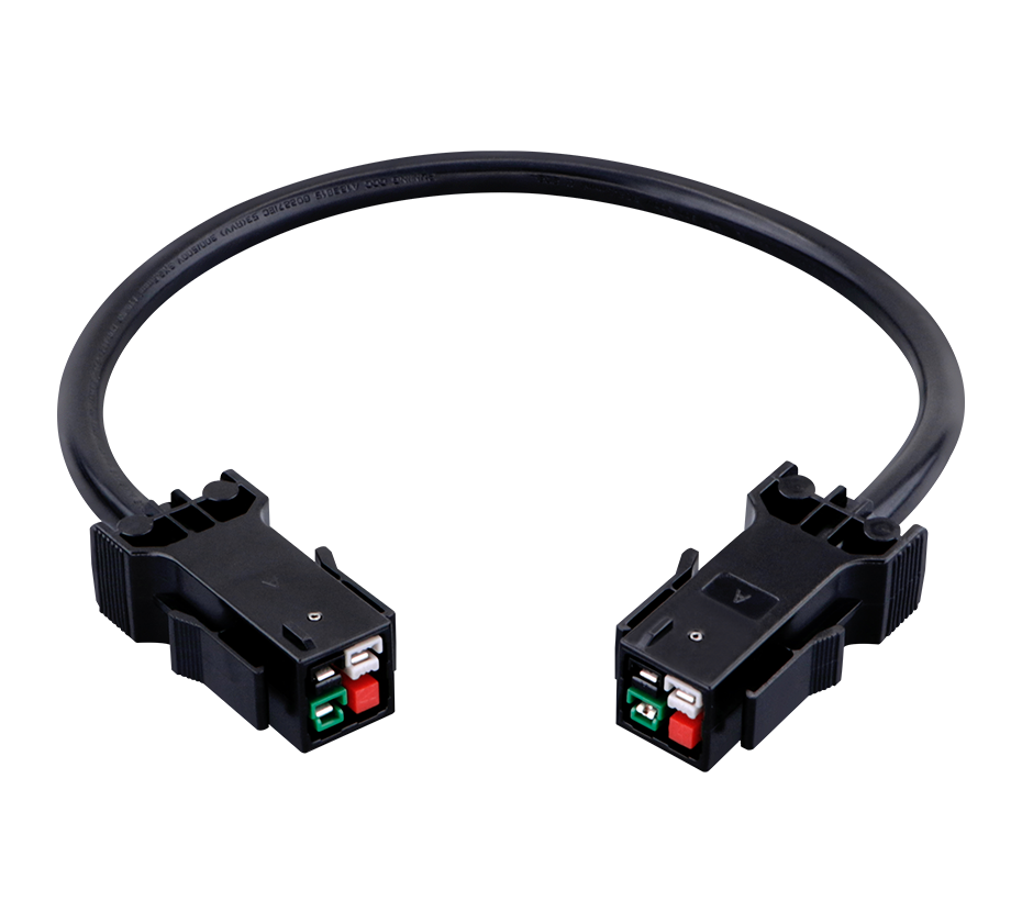
7. Industry Standards and Qualification Frameworks
7.1 Key Standards for Telecom Connectors
The qualification of power connectors for telecom applications is governed by a complex web of international, regional, and industry-specific standards. Understanding this standards landscape is essential for both connector manufacturers and equipment designers specifying connectors for 5G infrastructure.
IEC 61984 (Connectors – Safety requirements and tests) is the foundational international standard for connector safety. It specifies requirements for protection against electric shock, temperature rise, and fire, as well as test methods for verifying compliance. Connectors certified to IEC 61984, such as the Amphenol Amphe-TVS, have demonstrated compliance with comprehensive safety requirements.
UL 1977 (Component Connectors for Use in Data, Signal, Control and Power Applications) is the Underwriters Laboratories standard for connectors used in North American markets. It covers requirements for current-carrying capacity, temperature rise, dielectric withstand voltage, and mechanical durability.
EIA-364 (Electrical Connector/Socket Test Procedures Including Environmental Classifications) is a comprehensive test standard developed by the Electronic Components Industry Association (now part of ECIA). It defines hundreds of test methods for evaluating connector performance, including contact resistance, insulation resistance, dielectric withstanding voltage, vibration, shock, thermal shock, humidity, and salt spray. The FCI 92250-588 specification references EIA-364 series standards.
Telcordia GR-326 (Generic Requirements for Singlemode Optical Connectors) and related Telcordia standards (formerly Bellcore) are widely referenced in the telecommunications industry, though they focus primarily on fiber optic connectors. For power connectors, Telcordia GR-1217 (Generic Requirements for Separable Electrical Connectors Used in Telecommunications Hardware) provides relevant requirements.
7.2 Material Compliance: RoHS, REACH, and Beyond
Environmental regulations increasingly affect connector material selection and qualification. The RoHS (Restriction of Hazardous Substances) directive, originally adopted by the European Union in 2003 and subsequently updated, restricts the use of lead, mercury, cadmium, hexavalent chromium, polybrominated biphenyls (PBB), and polybrominated diphenyl ethers (PBDE) in electrical and electronic equipment. Virtually all connectors surveyed for this analysis are RoHS compliant, reflecting the industry’s near-universal adoption of RoHS requirements as a baseline.
REACH (Registration, Evaluation, Authorisation and Restriction of Chemicals) is a broader European Union regulation that addresses the production and use of chemical substances and their potential impacts on human health and the environment. REACH compliance requires that connector manufacturers understand and manage the chemical substances present in their products, including any Substances of Very High Concern (SVHC) that may be present above threshold concentrations. The Molex 95043-2881 and TE 1479795-1 connectors both specify REACH SVHC compliance.
Beyond regulatory requirements, many equipment manufacturers maintain their own restricted substance lists (RSLs) that may be more stringent than RoHS or REACH. Connector manufacturers must navigate these varying requirements to serve global markets.
7.3 Qualification Testing for 5G Power Connectors
The qualification of a power connector for 5G base station applications typically involves a comprehensive test program encompassing electrical, mechanical, and environmental performance. While specific requirements vary by equipment manufacturer, a typical qualification protocol might include:
Electrical tests: Contact resistance (initial and after environmental exposure), insulation resistance, dielectric withstanding voltage (hipot), current cycling, and temperature rise under load.
Mechanical tests: Mating and unmating forces, contact retention force, vibration (sinusoidal and random), mechanical shock, and durability (repeated mating cycles).
Environmental tests: Thermal shock, humidity (steady state and cyclic), salt spray (for outdoor connectors), and IP rating verification (dust and water ingress).
Material tests: Flammability (UL 94), glow wire (if applicable), and material composition analysis (RoHS, REACH).
The Amphe-TVS connector’s specifications—IP67 protection, 500 mating cycles, 500-hour salt spray, -40°C to +100°C operating temperature, and IEC 61984 certification—provide a representative example of the qualification level expected for 5G base station power connectors.
8. Future Trends and Emerging Requirements
8.1 Higher Power Densities and Current Ratings
The trajectory of 5G and future 6G development points toward continued increases in power density and current requirements. While current 5G macro base stations may draw 3-5 kW per radio unit, future systems with higher-order MIMO (e.g., 512 or 1024 antenna elements) and wider bandwidths could demand significantly more. This trend will drive connector designs toward higher current ratings, improved thermal management, and reduced contact resistance.
Meeting these requirements may require further advances in copper alloy technology. The Cu-Cr-Zr system described in CN113943874B represents the current state of the art for high-conductivity, high-strength connector materials, but even this alloy achieves only about 80% IACS conductivity. Research into copper-graphene composites, carbon nanotube-reinforced copper, and other advanced materials may eventually yield conductivity-strength combinations that are currently unattainable with conventional metallurgy.
8.2 Miniaturization and High-Density Interconnects
The space constraints in 5G equipment—particularly in massive MIMO antenna units where dozens or hundreds of transceiver chains must be accommodated in a compact housing—are driving connector miniaturization. Smaller connectors with higher contact density are needed, but reducing connector size while maintaining current rating and environmental sealing presents significant engineering challenges. The balance between current capacity (which favors larger conductors and contact areas) and miniaturization (which favors smaller features) will continue to drive innovation in contact design and materials.
8.3 Integration of Power and Signal
There is a growing trend toward connectors that integrate power and signal transmission in a single interface. This approach reduces the number of separate connectors, simplifies cable management, and can improve reliability by reducing the number of failure points. However, integrating power and signal in one connector introduces challenges related to crosstalk, impedance control, and isolation between the power and signal circuits. Connectors like the NEUTRIK USB Type-C 5G chassis connector, which provides both 100W power delivery and 5Gbps data transmission, represent early examples of this trend.
8.4 Sustainability and Circular Economy
The telecommunications industry is increasingly focused on sustainability, driven by both regulatory requirements and corporate environmental commitments. Connector designs are beginning to reflect this focus through the use of recycled materials, design for disassembly and recycling, and reduced material content. The shift toward halogen-free flame retardants, discussed in Section 3.3, is one example of how environmental considerations are shaping connector material selection.
8.5 Advanced Thermal Management
As power densities increase, thermal management becomes an increasingly critical design consideration for power connectors. Passive cooling through natural convection may become insufficient for the most demanding applications, potentially requiring connectors with integrated heat spreading or active cooling features. The thermal interface between the connector and the equipment housing, as well as the thermal path within the connector itself, will require careful engineering to ensure that contact temperatures remain within acceptable limits.
The 5G power supply system connector represents a convergence of advanced materials science, precision mechanical engineering, and rigorous qualification testing. From the Cu-Cr-Zr alloys that provide the optimal balance of conductivity and strength for high-current contacts, to the glass-filled thermoplastics and modified PPE blends that deliver flame retardance without compromising electrical or mechanical performance, to the sealing technologies and architectural designs that enable reliable operation in harsh outdoor environments, every aspect of the modern 5G power connector reflects decades of accumulated engineering knowledge and continuous innovation.
As 5G deployment continues to accelerate worldwide, and as research and development activities increasingly turn toward the requirements of 6G and beyond, the demands on power connectors will only intensify. Higher current ratings, greater power density, improved thermal performance, and even more stringent reliability and safety requirements will challenge connector designers and materials engineers to push the boundaries of what is achievable. The connector industry’s response to these challenges—through advances in copper alloy metallurgy, flame-retardant polymer chemistry, contact geometry optimization, and qualification testing methodologies—will play a critical but often unheralded role in enabling the next generation of wireless communication technology.
For equipment designers and system architects, a thorough understanding of the capabilities and limitations of power connectors is essential for ensuring the reliability and performance of 5G infrastructure. The connector is not merely a passive component but an active enabler of system performance, and its selection and qualification deserve the same rigorous attention as any other critical component in the power delivery chain.
 Yang.taya@aitmpower.com
Tel: 15382891313
Phone: 0769-88878951
Fax: 0769-88878955
Wechat: 15382891313


 CN
 CN
 Home >


