
 2026-10-14
 4
Abstract
Motor connectors constitute a specialized category of electromechanical interconnection devices designed specifically for transmitting power, control signals, and feedback data between electric motors and their associated drive electronics, control systems, or power sources. Unlike general-purpose connectors, motor connectors must withstand demanding operational conditions including continuous vibration, thermal cycling, exposure to oils and coolants, and the electrical stresses inherent to inductive motor loads. This comprehensive analysis examines the technical foundations, design considerations, product architectures, application scenarios, and selection methodologies for motor connectors, with particular emphasis on servo motor interfaces, M12 power connectors, M23 drive connectors, and emerging hybrid power-signal solutions. The discussion extends to critical performance parameters such as current rating, voltage capability, ingress protection, vibration resistance, and electromagnetic compatibility, providing engineers and system integrators with a thorough framework for connector selection and implementation in industrial automation and motion control applications.
1. Introduction
The reliable transmission of electrical power and control signals to electric motors represents a fundamental challenge in industrial automation, robotics, and manufacturing systems. Motor connectors serve as the critical interface between motors and their drive systems, bridging the gap between stationary control cabinets and moving machine elements. The evolution of motor connector technology reflects broader trends in industrial connectivity: increasing miniaturization, higher power density, enhanced environmental protection, and the integration of multiple signal types within single connector interfaces.
The historical development of motor connectors parallels the progression of motor control technology itself. Early motor connections relied on simple terminal blocks and hardwired junctions, approaches that offered minimal protection against environmental factors and provided no facility for rapid disconnection or replacement. The proliferation of servo motors and variable frequency drives beginning in the 1980s and 1990s created demand for specialized connector solutions capable of handling the unique electrical characteristics of motor drive systems—including high-frequency switching noise, common-mode voltages, and the need for precise encoder feedback transmission.
Contemporary motor connectors must satisfy an increasingly complex set of requirements. Electrically, they must carry currents ranging from a few amperes for small servo motors to hundreds of amperes for large industrial drives, while simultaneously transmitting low-level encoder signals that are susceptible to electromagnetic interference. Mechanically, they must maintain contact integrity under continuous vibration and shock loading, resist ingress of dust, water, and chemicals, and facilitate rapid installation and replacement without specialized tooling. Thermally, they must dissipate heat generated by contact resistance and ambient conditions while maintaining insulation integrity at temperatures potentially exceeding 125°C. Finally, they must provide reliable performance over thousands of mating cycles throughout the operational lifetime of the equipment they serve.
This analysis provides a systematic examination of motor connector technology, beginning with fundamental design considerations and proceeding through detailed discussions of major connector families, application scenarios, and selection criteria. The objective is to furnish a comprehensive reference for engineers tasked with specifying, implementing, or maintaining motor connection systems in industrial environments.
2. Design Considerations and Technical Requirements
2.1 Electrical Characteristics
The electrical design of motor connectors must address several distinctive challenges that differentiate them from general-purpose interconnection devices. The most fundamental consideration is current-carrying capacity, which determines the conductor cross-section, contact geometry, and thermal management requirements. Motor connectors for servo applications typically carry rated currents between 5 A and 30 A per power contact, though high-power industrial motor connectors may be rated for significantly higher currents. The current rating is not merely a function of conductor size but depends critically on the contact resistance, which must remain stable over the connector's service life to prevent excessive heating at the contact interface.
Voltage rating constitutes a second critical electrical parameter. Servo motor power connectors commonly operate at voltages up to 630 V AC/DC, accommodating the DC bus voltages typical of modern servo drive systems as well as the AC line voltages found in industrial power distribution. The voltage rating of a connector reflects not only the dielectric strength of its insulation materials but also the creepage and clearance distances between conductive elements, which must be maintained under all operating and environmental conditions.
The inductive nature of motor loads introduces additional electrical stresses that connector designers must accommodate. When a motor circuit is interrupted—whether during normal operation or under fault conditions—the collapsing magnetic field generates a voltage transient that can significantly exceed the nominal system voltage. This transient can cause arcing at the contact separation point, leading to contact erosion and potential failure. Motor connectors therefore require contact materials and geometries that can withstand these transient events without degradation, often employing silver or gold plating over copper alloy substrates to provide both low contact resistance and resistance to arc-induced erosion.
Electromagnetic compatibility (EMC) represents a particularly nuanced electrical consideration for motor connectors, especially those carrying encoder or other signal-level circuits. The pulse-width modulated output of modern motor drives generates high-frequency noise that can couple into signal conductors through capacitive and inductive mechanisms. To combat this interference, motor connectors designed for servo applications frequently incorporate 360-degree shielding, wherein a metallic shell completely surrounds the contact assembly and provides a low-impedance path to ground for interfering signals. The effectiveness of this shielding depends on maintaining continuous electrical contact between the connector shell, the cable shield, and the equipment chassis throughout the mated condition.
2.2 Mechanical Design and Environmental Protection
Mechanical robustness is a defining characteristic of motor connectors, distinguishing them from connectors intended for benign office or consumer environments. Industrial motor applications subject connectors to continuous vibration from rotating machinery, shock loads from material handling operations, and repeated mating and unmating during maintenance activities. The contact system must maintain stable electrical connection despite these mechanical stresses, requiring contact designs that provide consistent normal force over many cycles and locking mechanisms that prevent accidental disconnection.
Vibration resistance is achieved through several complementary design strategies. Contact systems employing hyperboloid or spring-loaded socket designs provide multiple points of contact per pin, ensuring that at least some contact points remain engaged even under dynamic loading conditions. Secondary locking mechanisms, including threaded coupling nuts, bayonet locks, and lever-actuated retention systems, maintain the mated condition under vibration that might otherwise cause gradual loosening. The housing materials themselves must resist fatigue cracking under continuous vibration, leading to the use of glass-filled thermoplastics and die-cast metal housings in demanding applications.
Ingress protection ratings, specified according to IEC 60529, quantify a connector's resistance to dust and water intrusion. The IP rating consists of two digits: the first indicating protection against solid objects (0-6) and the second indicating protection against liquids (0-8). Motor connectors commonly achieve IP67 ratings, indicating complete protection against dust ingress and protection against temporary immersion in water up to 1 meter depth. Some applications, particularly those involving washdown or outdoor exposure, require IP68 ratings indicating protection against continuous immersion under specified conditions. Achieving these ratings requires careful design of sealing interfaces, including face seals between mating halves, cable entry seals, and sealing of any panel mounting interfaces.
Temperature range constitutes another critical environmental parameter. Motor connectors typically operate over temperature ranges from -40°C to +125°C, with the upper limit determined by the thermal stability of insulation and sealing materials. The temperature rating of a connector reflects the maximum continuous operating temperature at which the connector can maintain its rated electrical and mechanical performance. Intermittent excursions to higher temperatures may be permissible if the connector's thermal time constant is sufficient to prevent the critical internal temperature from exceeding the material limits.
Chemical resistance assumes particular importance in motor applications where lubricants, coolants, hydraulic fluids, and cleaning agents may contact the connector. Seal materials, typically Viton or nitrile rubber for demanding applications, must resist swelling, hardening, or degradation upon exposure to these substances. Housing materials must similarly resist chemical attack, with nickel-plated die-cast zinc and engineered thermoplastics offering good resistance to common industrial chemicals.
2.3 Mating Cycle Durability
The mating cycle rating of a motor connector specifies the number of complete connection and disconnection operations the connector can withstand while maintaining its specified performance characteristics. This parameter varies widely across motor connector types, reflecting the diverse application requirements they serve. Micro motor connectors intended for compact servo applications may be rated for 100 mating cycles, appropriate for equipment where motor connections are established during assembly and rarely disturbed thereafter. General-purpose industrial connectors may achieve ratings of 500 cycles or more, while connectors intended for frequently reconfigured systems may be rated for thousands of cycles.
Mating cycle durability depends on several factors, including contact plating thickness and composition, contact geometry, and the design of the retention mechanism. Gold plating, while offering excellent corrosion resistance and stable contact resistance, is relatively soft and subject to wear; thicker gold layers (measured in microinches or micrometers) provide longer cycle life. Contact designs that minimize sliding motion during mating and unmating reduce wear on plated surfaces, extending useful life. The locking mechanism must also withstand repeated actuation without excessive wear or loss of retention force.
2.4 Standards and Certifications
Motor connectors intended for industrial applications are typically certified to one or more international standards, providing assurance of safety, performance, and interoperability. Underwriters Laboratories (UL) certification addresses electrical safety requirements, including insulation integrity, temperature rise limits under rated current, and resistance to abnormal operating conditions. TÜV certification, particularly common for European-manufactured connectors, similarly addresses safety and performance requirements under European standards. The presence of these certifications indicates that the connector has been independently tested and found to comply with applicable safety standards, a prerequisite for acceptance in many industrial installations.
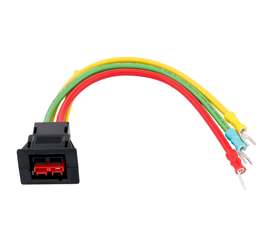
3. Major Motor Connector Categories
3.1 Micro Motor Connectors for Compact Servo Applications
Micro motor connectors represent a specialized solution for the growing market of compact servo motors used in robotics, laboratory automation, and small-scale motion control systems. These connectors address the fundamental challenge of interfacing three distinct functional groups—power, brake, and encoder—within the confined space available on miniature motor housings. The design philosophy emphasizes hybrid integration, wherein multiple signal types share a single connector interface, reducing the number of separate cables and connectors required and simplifying installation.
A representative implementation combines power and brake functions into a single connector while providing a separate interface for encoder signals. The power section typically accommodates the three-phase AC or DC power connections (U, V, W) plus protective earth (PE), while the brake section provides two additional contacts for the motor holding brake circuit. The encoder connector, physically smaller to reflect the lower current requirements of signal circuits, provides from 2 to 16 positions depending on the encoder type and communication protocol employed.
The electrical ratings of micro motor connectors reflect their intended application domain. Power contacts are typically rated for 5 A at voltages up to 630 V AC/DC, sufficient for servo motors in the fractional to low single-digit kilowatt range. Brake contacts, carrying only the brake actuation current, are rated for lower currents, typically 2 A. The encoder contacts carry microampere to milliampere-level signals and are rated accordingly, with voltage ratings typically in the 30-100 V DC range.
The environmental performance of micro motor connectors is particularly notable given their compact dimensions. Achieving IP67 sealing in a connector small enough for miniature servo motors requires careful attention to gasket design, contact spacing, and housing construction. The rectangular configuration of many micro motor connectors, as opposed to circular designs, facilitates sealing by providing continuous sealing surfaces around the connector perimeter. Vibration resistance is achieved through robust contact designs and secure locking mechanisms, with the connectors rated for the continuous vibration levels typical of servo motor operation.
3.2 M12 Power Connectors
The M12 connector system, originally developed for sensor and actuator connections in factory automation, has evolved to include power versions capable of carrying the currents required by small motors and drives. M12 power connectors, particularly those employing L-coding, provide a compact and robust solution for applications requiring high current at low voltage, including linear drives, brushless DC motors, and stepper motors.
The M12 power connector configuration designated for motor applications typically provides five contacts rated for 16 A each at voltages up to 63 V AC/DC. The L-coding, a keying arrangement that prevents mismating with standard M12 signal connectors, ensures that power connectors cannot be inadvertently connected to signal circuits. The 5-core PUR cable associated with these connectors employs 1.5 mm² conductors, balancing current-carrying capacity against the flexibility required for moving machine applications.
One of the defining advantages of the M12 power system is its integration within the broader M12 connectivity ecosystem. An extensive range of M12 connectors, adapters, bulkhead fittings, and cable assemblies is available from multiple manufacturers, providing flexibility in system design and simplifying procurement and maintenance. The push-on conduit connection feature integrated into many M12 power connectors allows flexible corrugated conduit to be anchored directly to the connector, providing mechanical protection for the cable while maintaining the environmental sealing of the connector interface.
The compact dimensions of M12 connectors make them particularly suitable for applications where space is at a premium. The threaded coupling mechanism, standardized across the M12 system, provides secure retention under vibration while facilitating rapid connection and disconnection. For motor applications where the connector may be subject to frequent maintenance activity, the M12 system offers a favorable balance of compact size, robust construction, and ease of use.
3.3 M23 Drive Connectors
The M23 connector system occupies a higher tier of the motor connector hierarchy, providing the power and signal capacity required by medium to large servo motors and high-performance drive systems. M23 drive connectors are characterized by their larger physical size relative to M12 connectors, accommodating larger conductor cross-sections and providing higher current ratings. A representative M23 drive connector offers eight poles, with power contacts rated at 28 A per pin and signal contacts rated at 8 A, operating at voltages up to 630 V AC/DC.
The M23 system's 360-degree shielding provides exceptional electromagnetic compatibility, an essential characteristic for servo applications where encoder signals must be transmitted alongside power conductors carrying high-frequency switching currents. The shielding effectiveness of the M23 design results from the complete metallic shell that surrounds the contact assembly, combined with careful attention to the electrical continuity between the shell, the cable shield, and the equipment ground. This shielding, combined with the twisted-pair and individually shielded construction of the associated cable, ensures that encoder signals remain free from the interference that could otherwise cause positioning errors or drive faults.
The locking mechanism of M23 drive connectors reflects the demanding requirements of servo motor applications. A hexagonal locking nut, tightened to a specified torque using a calibrated torque wrench, ensures secure retention under the vibration levels encountered in servo systems. A coding arrow on the housing provides a visual indication of correct alignment, facilitating installation in confined spaces where tactile alignment may be difficult. The locking mechanism is designed to maintain sealing integrity even when exposed to oils and lubricants, a common condition in machine tool and metal forming applications.
M23 drive connectors are frequently specified with high-quality original equipment manufacturer cables, particularly those compatible with Siemens servo systems and other major drive platforms. The availability of pre-assembled cable assemblies with M23 connectors on one end and the appropriate motor or drive-end terminations on the other simplifies system integration and ensures optimal electrical performance.
3.4 Hybrid Power-Signal Connectors
The trend toward integrating multiple signal types within single connector interfaces has produced a class of hybrid motor connectors that combine power and signal circuits in a unified housing. These connectors address the practical reality that many motor applications require both power transmission and feedback signal transmission, and that separate connectors for each function increase cable count, installation complexity, and potential failure points.
A representative hybrid motor connector integrates power and signal lines within a single connector body, employing a lever-lock mechanism for easy handling and providing strong vibration resistance. The connector is rated for IP67 protection when mated, with power pins rated at 7 A and signal pins at 1 A. Voltage ratings of 1500 V AC for power circuits and 500 V AC for signal circuits reflect the differing dielectric requirements of the two circuit types. Operating temperature range extends from -40°C to +105°C, suitable for most industrial environments.
The integration of power and signal within a single connector requires careful attention to internal isolation between the two circuit groups. Creepage and clearance distances must be maintained between power and signal contacts to prevent voltage breakdown, while the connector geometry must physically separate the two groups to prevent signal degradation from power circuit noise. The mechanical design must also ensure that the connector cannot be partially mated in a way that energizes power circuits while leaving signal circuits unconnected, or vice versa.
Hybrid connectors find application in electric motors, powertrains, and other systems where the savings in cable count, installation time, and space justify the increased complexity of the connector itself. As motor systems become more integrated and compact, the demand for hybrid power-signal connectors is expected to continue growing.
3.5 Heavy-Duty and Specialized Motor Connectors
Beyond the standardized connector families discussed above, a range of heavy-duty and specialized motor connectors address applications with requirements beyond the capabilities of standard products. Motor connection housings meeting IP65 requirements, such as the HM-10 series, provide protection against dust and water spray while accommodating the large conductor sizes and high currents associated with industrial motors. These housings often employ die-cast metal construction for mechanical robustness and thermal dissipation, with powder-coated finishes offering corrosion resistance.
For applications requiring termination of magnet wire directly to connector contacts, specialized terminals such as the AMPLIVAR series employ serrated crimp barrels that pierce wire insulation without stripping, creating solderless and airtight connections. These terminals are compatible with high-throughput automated termination systems and support multiple magnet wires within a single crimp, making them particularly suitable for high-volume motor manufacturing. The elimination of wire stripping and soldering reduces process steps, eliminates potential contamination from flux and solder residues, and avoids the wire embrittlement that can result from thermal termination processes.
LS1 series connectors represent another specialized motor connector family, offering configurations with 5+PE, 3+PE+4, or 3+PE+5 contacts and rated currents up to 30 A. Available in both traditional screw-coupled and push-pull versions, these connectors employ crimp contacts for optimal connection quality and provide 360-degree screening for electromagnetic compatibility. The LS1 series accommodates cable diameters from 9 to 17 mm and offers 500 mating cycles, positioning them between the compact M12 system and larger heavy-duty connectors in terms of capacity and robustness.
4. Application Scenarios and Selection Criteria
4.1 Servo Motor Applications
Servo motor applications represent perhaps the most demanding environment for motor connectors, combining high current and voltage requirements with the need for precise encoder signal transmission and resistance to continuous vibration. The selection of connectors for servo applications must consider the complete system architecture, including the motor, drive, cable, and connector interfaces.
For compact servo motors in robotics and laboratory automation, micro motor connectors offer an optimal balance of size, performance, and integration. The hybrid power-brake connector combined with a separate encoder connector provides the functional integration required while maintaining manageable connector dimensions. The IP67 rating ensures protection against the cleaning agents and occasional liquid exposure common in laboratory and light industrial environments.
For medium and large servo motors in machine tool, packaging, and material handling applications, M23 drive connectors provide the power capacity and shielding effectiveness required. The 28 A per pin power rating accommodates servo motors in the multiple kilowatt range, while the 360-degree shielding ensures encoder signal integrity in the presence of the high-frequency noise generated by modern servo drives. The robust locking mechanism and oil-resistant sealing materials ensure reliable operation in the demanding conditions of industrial production environments.
4.2 Asynchronous Motor Applications
Asynchronous (induction) motors remain the workhorses of industrial drive systems, employed in applications ranging from simple fan and pump drives to complex process control systems. Motor connectors for asynchronous motors must accommodate the three-phase power connections plus protective earth, and may optionally include auxiliary contacts for thermal protection devices, space heaters, or other motor-integrated sensors.
For small asynchronous motors up to 7.5 kW, the MQ15-X-Power range offers a cost-effective connectivity solution with three power contacts rated at 16 A, PE, and two auxiliary contacts. The over-molded plug construction ensures IP67 sealing when mated and eliminates the risk of wiring errors during field installation. The M20 bulkhead connectors included in the range can be mounted directly on the motor terminal box, often utilizing the knockout provided by the motor manufacturer, and tightened using the supplied back nut. This mounting arrangement provides secure strain relief while maintaining the environmental sealing of the motor enclosure.
4.3 Stepper and Brushless DC Motor Applications
Stepper motors and brushless DC (BLDC) motors, characterized by their relatively low operating voltages and moderate current requirements, are well-served by the M12 power connector system. The L-coded M12 connector, with its five contacts rated at 16 A each and voltage rating of 63 V AC/DC, matches the electrical characteristics of these motor types while providing the compact dimensions and system integration advantages of the M12 platform.
The 1.5 mm² conductor cross-section of the associated cable provides an appropriate balance between current-carrying capacity and flexibility for the moving cable applications typical of stepper and BLDC motor installations. The push-on conduit connection facilitates the use of corrugated conduit for mechanical protection in applications where the cable may be subject to abrasion or impact.
4.4 Selection Methodology
The selection of an appropriate motor connector requires systematic evaluation of application requirements against connector capabilities. The following framework provides a structured approach to motor connector selection:
Electrical Requirements Assessment: The first step involves quantifying the electrical parameters of the motor application, including rated current per phase, operating voltage, number of power and signal contacts required, and any special requirements such as brake circuits or thermal sensor connections. The connector's current rating must equal or exceed the application's continuous current requirement, with margin for overload conditions. Voltage rating must accommodate the maximum system voltage including transient overvoltages.
Environmental Requirements Assessment: The operating environment determines the required ingress protection rating, temperature range, chemical resistance, and vibration resistance. Applications involving washdown or outdoor exposure require IP67 or higher ratings. High-temperature environments require attention to the connector's temperature rating and the thermal derating of current capacity at elevated temperatures. Exposure to oils, coolants, or cleaning agents requires verification of seal and housing material compatibility.
Mechanical Requirements Assessment: The physical constraints of the installation influence connector selection. Available space determines the maximum connector dimensions, while the required cable diameter and flexibility determine the cable entry provisions. The required mating cycle life influences the choice of contact plating and locking mechanism. The need for rapid connection or disconnection may favor push-pull or lever-actuated locking mechanisms over threaded coupling.
Signal Integrity Requirements Assessment: For motor applications involving encoder or other signal circuits, the connector's shielding effectiveness and internal isolation between power and signal circuits become critical selection criteria. The data rate and signal level of the encoder system determine the required shielding performance and contact spacing.
Standards and Certification Requirements: The applicable safety standards for the target market determine the required certifications, such as UL or TÜV. The connector selection must include verification that appropriate certifications are available and current.
5. Installation, Maintenance, and Reliability Considerations
5.1 Installation Best Practices
Proper installation of motor connectors is essential for achieving the performance and reliability designed into the connector. Several installation factors merit particular attention:
Cable Preparation: The cable preparation must match the connector's requirements, including the correct strip length for the contact termination, preservation of shielding integrity for shielded connectors, and proper preparation of the cable jacket for the strain relief and sealing provisions. For crimp-terminated contacts, the correct crimp tooling and crimp height are essential for achieving the specified contact resistance and pull-out strength.
Contact Insertion: Contacts must be fully seated in the connector housing and secured by any retention mechanism. Incomplete insertion can result in contact recession, leading to intermittent connection or arcing. The audible click or tactile feedback provided by properly seated contacts should be verified during installation.
Sealing Verification: For connectors with separate sealing components, including panel gaskets and cable seals, verification that these components are properly positioned and undamaged is essential for achieving the rated ingress protection. Over-torquing of sealing nuts can deform seals and compromise their performance, while under-torquing can leave gaps that permit ingress.
Locking and Strain Relief: The connector locking mechanism must be fully engaged and, where applicable, tightened to the specified torque. Strain relief provisions must be properly engaged to prevent mechanical loads from being transmitted to the electrical connections.
5.2 Maintenance and Inspection
Motor connectors in industrial service benefit from periodic inspection and maintenance to identify and address potential issues before they cause equipment failure. Inspection activities should include:
Visual Examination: Checking for signs of overheating (discoloration, deformation), contamination (dust, oil, moisture), mechanical damage (cracks, corrosion), and proper engagement of locking mechanisms.
Electrical Testing: Measuring contact resistance to detect degradation from wear, corrosion, or contamination. Comparing measured values against baseline data and against the connector's specification limits identifies contacts requiring attention.
Seal Inspection: Examining sealing components for compression set, cracking, or other degradation that could compromise ingress protection. Replacing seals at scheduled intervals may be appropriate for connectors in demanding environments.
Cleaning and Reconditioning: Cleaning contact surfaces and sealing interfaces with appropriate solvents and applying contact lubricants where specified can extend connector life. Damaged or worn components should be replaced.
5.3 Failure Modes and Mitigation
Understanding the failure modes that can affect motor connectors enables the implementation of preventive measures:
Contact Degradation: Progressive increase in contact resistance due to wear, corrosion, or contamination can lead to excessive heating and eventual failure. Mitigation includes specifying connectors with appropriate mating cycle ratings for the application, maintaining sealing integrity to exclude contaminants, and periodic contact resistance testing.
Insulation Failure: Breakdown of insulation materials due to thermal degradation, chemical attack, or voltage stress can result in short circuits or ground faults. Mitigation includes verifying that the connector's temperature and chemical ratings are appropriate for the application, and that voltage transients are within the connector's capability.
Seal Failure: Loss of ingress protection due to seal degradation, damage, or improper installation can result in moisture or contaminant ingress, leading to corrosion or insulation failure. Mitigation includes proper installation practices, periodic seal inspection and replacement, and protection of the connector from mechanical damage.
Mechanical Failure: Breakage of housing components, locking mechanisms, or strain relief provisions due to mechanical stress or fatigue can result in loss of connection or loss of sealing. Mitigation includes proper cable routing and support, avoiding excessive force on connectors, and selection of connectors with appropriate mechanical robustness for the application.
6. Future Trends and Emerging Technologies
The evolution of motor connector technology continues, driven by broader trends in industrial automation and motor control. Several emerging developments merit attention:
Increased Power Density: As motor drives become more compact and power-dense, connectors must follow suit, carrying higher currents in smaller packages. Advances in contact materials, geometries, and thermal management will enable continued increases in power density.
Higher Data Rates: The increasing use of digital encoder interfaces and real-time Ethernet protocols in motion control applications is driving demand for motor connectors capable of transmitting higher data rates alongside power. Connectors integrating power and high-speed data transmission will become more prevalent.
Enhanced Diagnostics: The integration of sensors and diagnostic capabilities into motor connectors—including temperature monitoring, contact wear detection, and connection verification—can enable predictive maintenance and reduce unplanned downtime.
Sustainability and Recyclability: Growing attention to environmental sustainability is driving interest in connectors that are more easily recycled at end of life, and in materials with reduced environmental impact. Design for disassembly and material selection will become increasingly important considerations.
Standardization and Interoperability: Continued standardization of motor connector interfaces, particularly for servo applications, can reduce the proliferation of proprietary solutions and simplify system integration. Industry consortia and standards bodies will continue to play a role in defining common interfaces.
Motor connectors constitute a critical enabling technology for industrial automation and motion control systems, providing the essential interface between electric motors and their drive and control electronics. The demanding requirements of motor applications—high current and voltage, environmental exposure, continuous vibration, and the need for reliable signal transmission—have driven the development of specialized connector designs that address these challenges through careful engineering of contact systems, sealing provisions, locking mechanisms, and shielding.
The major motor connector families—micro motor connectors for compact servo applications, M12 power connectors for small motors and drives, M23 drive connectors for medium and large servo systems, and hybrid power-signal connectors for integrated motor interfaces—each address specific segments of the motor application spectrum. Selection of the appropriate connector requires systematic evaluation of electrical, environmental, mechanical, and signal integrity requirements against the capabilities of available products.
Proper installation, maintenance, and application of motor connectors are essential for achieving the reliability and performance designed into these components. Understanding the failure modes that can affect motor connectors and implementing appropriate preventive measures can extend connector life and reduce unplanned downtime.
As motor and drive technology continues to evolve toward higher power density, greater integration, and enhanced diagnostic capability, motor connectors will continue to advance in parallel, providing the reliable interconnection solutions required by increasingly demanding industrial applications. The fundamental principles of connector design—reliable electrical contact, environmental protection, mechanical robustness, and electromagnetic compatibility—will remain constant, even as the specific implementations evolve to meet new challenges.
 Yang.taya@aitmpower.com
Tel: 15382891313
Phone: 0769-88878951
Fax: 0769-88878955
Wechat: 15382891313


 CN
 CN
 Home >


