
 2026-10-14
 3
Introduction
Communications power terminals form the foundational infrastructure of every telecommunications network, providing the critical interface between power sources and the equipment that keeps networks operational. From the massive power distribution frames in central offices to the compact terminal blocks inside remote radio units, these components ensure that electrical power reaches communications equipment reliably, safely, and efficiently.
The evolution of communications power terminals has closely tracked the broader transformation of telecommunications technology. Early telephone exchanges relied on simple screw-terminal connections for their relatively modest power requirements. Today's 5G networks, with their dramatically higher power consumption and densely packed equipment, demand terminal solutions that can handle hundreds of amperes while maintaining signal integrity, environmental protection, and ease of maintenance in increasingly challenging deployment scenarios.
This article examines the full spectrum of communications power terminals, from their fundamental design principles and material specifications to their applications across different segments of telecommunications infrastructure.
Classification and Types of Communications Power Terminals
Communications power terminals can be broadly classified into several categories based on their construction, connection method, and intended application. Understanding these classifications is essential for selecting the appropriate terminal technology for a given application.
Screw Clamp Terminal Blocks
Screw clamp terminal blocks represent the most traditional and widely deployed terminal technology in telecommunications infrastructure. These terminals use a threaded fastener to mechanically compress the conductor against a current-carrying element, establishing both electrical contact and mechanical retention.
The primary advantage of screw clamp technology is its high reliability and suitability for high current applications. The mechanical pressure provided by a properly torqued screw creates a stable, low-resistance contact that can carry substantial currents without excessive heating. The TE Connectivity ENTRELEC CBS95-4P compact power block, for example, is a screw clamp terminal block that handles 95mm² (3/0 AWG) conductors at 1000V AC/DC and 232A (IEC/UL) using screw clamp technology.
Screw clamp terminals are well-suited for applications where connections are made infrequently and where high current capacity is required, such as main power distribution panels, battery connections, and equipment input terminals. Their primary limitations include the time required for installation (each connection must be individually tightened to the specified torque) and the need for periodic re-torquing in some applications to compensate for conductor settling.
Spring Clamp and Push-In Terminal Blocks
Spring clamp terminals, also known as cage clamp terminals, use a spring mechanism to maintain pressure on the conductor. The push-in variant extends this concept by allowing the conductor to be inserted directly without tools, with the spring automatically providing the contact force.
Spring clamp technology offers several advantages over screw clamp terminals. Installation is significantly faster, particularly for push-in types. The spring force maintains constant pressure over time, eliminating the need for re-torquing. The design is inherently vibration-resistant, making it suitable for applications in mobile equipment or high-vibration environments.
Spring clamp terminals are increasingly preferred in telecommunications equipment where field installation speed and long-term reliability are priorities. They are particularly well-suited for factory automation, mobile machinery, and equipment where maintenance accessibility may be limited. The primary limitation of spring clamp technology is the reduced contact area compared to screw clamp designs, which can affect current-carrying capacity in very high-power applications.
Rigid Type Terminals
Rigid-type terminals are characterized by their hard thermoset or thermoplastic bases and housings, providing fixed channels with embedded metal clamps or screws to secure wires on a DIN rail or panel. These terminals are designed for applications where mechanical stability and electrical isolation are paramount.
The insulating body of rigid terminals is typically made from phenol-formaldehyde (Bakelite), PBT, or similar high-dielectric plastics. These materials are non-hygroscopic and withstand high voltages, making them suitable for power distribution applications. The touch-proof housing design covers live terminals for safety, and modular construction allows blocks to be snapped side-by-side on DIN rails or assembled into custom configurations.
Rigid terminals find application in control panels, power distribution boards, and telecom equipment where organizing twisted pairs or grounding bars is required. Their solid construction makes them resistant to vibration and ensures that torque settings and contact pressure are maintained over repeated cycles and temperature changes.
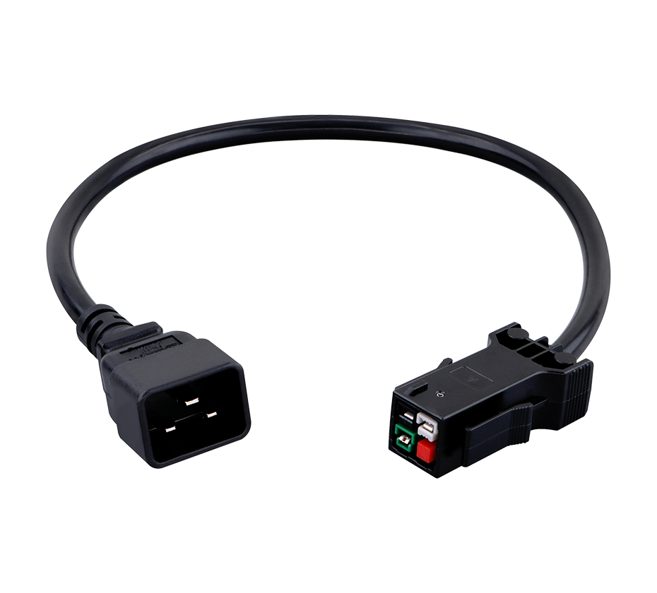
High-Power and Hybrid Connectors
At the upper end of the power spectrum, specialized high-power connectors are used for the main power feeds to telecommunications equipment. These connectors are designed to handle the highest current levels while maintaining safe operating temperatures and providing features such as hot-plug capability, keying to prevent mismating, and environmental sealing.
The Molex EXTreme Ten60Power Hybrid Power/Signal Connectors represent a sophisticated approach to high-power interconnection in telecommunications equipment. These connectors provide up to 260A per linear inch and are designed for board-to-board, wire-to-board, and panel-to-board applications. They support maximum voltages of 600V for power and 250V for signal, with maximum currents of 60.0A for board-to-board power and 50.0A for wire-to-board and panel-to-board power. The hybrid design allows power and signal connections to be made through a single connector, simplifying equipment design and reducing the number of separate connectors required.
The Amphenol Amphe-TVS is another high-power connector specifically designed for base station power applications. It is available in two insert pattern options: a 2-pole configuration suited for DC power needs and a 3-pole design tailored for AC power applications. The connector is rated for power applications up to 80A with proper contacts and features IP67 environmental protection, making it suitable for outdoor tower and rooftop installations.
Materials and Construction
The performance and reliability of communications power terminals depend fundamentally on the materials used in their construction. Conducting materials, insulating materials, and plating systems each contribute to the terminal's electrical, mechanical, and environmental performance.
Conducting Materials
The conducting elements of power terminals must provide low electrical resistance while maintaining mechanical strength and resistance to stress relaxation. Copper and its alloys are the predominant materials for this application, with the specific alloy selected based on the balance of conductivity, strength, and cost required by the application.
Pure copper offers the highest electrical conductivity but has relatively low mechanical strength. For terminal applications where spring properties are required, copper alloys such as brass, phosphor bronze, and beryllium copper are preferred. Brass offers a good balance of conductivity (approximately 28% to 50% IACS) and mechanical strength, making it suitable for many general-purpose terminal applications. Phosphor bronze provides better wear and corrosion resistance with somewhat lower conductivity, making it suitable for applications where durability is a priority. Beryllium copper offers the highest strength among common copper alloys while maintaining good conductivity, making it the material of choice for high-reliability spring contacts.
In high-power terminal blocks, the current-carrying elements may be made from copper or aluminum. The TE Connectivity CBS95-4P uses an aluminum tin-plated body, which offers weight savings compared to copper while still providing good electrical and thermal conductivity.
Insulating Materials
The insulating materials used in power terminals must provide electrical isolation between adjacent conductors, mechanical support for the conducting elements, and protection against environmental factors such as moisture, dust, and UV radiation. The material must maintain its dielectric strength and mechanical properties across the full operating temperature range and resist degradation over the equipment's service life.
Polyamide 6/6 (PA66) is one of the most common insulating materials for terminal blocks. It offers good dielectric properties, high temperature resistance, and UL94 V-0 flame retardancy. Polybutylene terephthalate (PBT) is another common choice, offering similar properties with somewhat better dimensional stability.
Phenolic resins, commonly known as Bakelite, have been used in terminal blocks for decades. Their non-hygroscopic nature and high dielectric strength make them particularly suitable for high-voltage applications. However, phenolic materials are generally more brittle than modern thermoplastics and are being replaced by PA66 and PBT in many applications.
Plating Systems
Plating systems applied to terminal contact surfaces serve multiple functions: reducing contact resistance, preventing corrosion, and improving wear resistance. The specific plating material and thickness are selected based on the application requirements, with gold, silver, and tin being the most common options.
Gold plating provides the most stable, low-resistance contact interface and is preferred for low-level signal applications and high-reliability power connections. The Kyocera AVX battery connectors use gold plating over a nickel underplate, with the gold thickness ranging from 0.4 to 0.8 μm depending on the application environment.
Silver plating offers higher conductivity than gold and is often preferred for high-power applications where minimizing contact resistance is critical. The Anderson Power Euro Battery Connector uses silver-plated copper contacts to provide excellent conductivity and superior mating cycle performance.
Tin plating is the most economical option and provides adequate performance for many general-purpose applications. However, tin is susceptible to oxidation and the formation of whiskers, which can cause short circuits in densely packed terminal arrangements. Tin-plated contacts are generally limited to applications where the contact force is sufficient to break through the oxide layer and where the risk of whisker-induced failures is acceptable.
Applications in Telecommunications Infrastructure
Communications power terminals find application across virtually every segment of telecommunications infrastructure, from the core network to the radio access network and into customer premises equipment.
Central Office and Data Center Power Distribution
In central offices and data centers, power terminals are used in the main DC power distribution systems that feed telecommunications equipment. These systems typically operate at -48V DC (positive ground) and use high-current terminal blocks to distribute power from rectifiers and battery strings to the equipment racks.
The terminal blocks used in these applications must handle continuous currents of hundreds of amperes while maintaining safe operating temperatures. The TE Connectivity CBS95-4P, with its 232A rating at 1000V, is representative of the high-power terminal blocks used in these applications. Its approvals to IEC 60947-7-1, UL-1059, and UL 486E ensure compliance with the relevant safety standards for telecommunications power distribution.
Base Station Power Systems
The 5G base station presents unique challenges for power terminal design. These systems combine high power requirements (11.5 to 14 kW average, with peaks to 19 kW) with outdoor environmental exposure and often limited space for equipment.
The power terminals used in base stations must maintain reliability despite temperature extremes, moisture, vibration, and potential exposure to pollutants. The Amphenol Amphe-TVS connector, with its IP67 environmental protection and operation over demanding temperature ranges, exemplifies the type of ruggedized terminal solution required for these applications.
Inside the base station enclosure, power terminal blocks distribute DC power from the backup battery system to the radio equipment. These terminals must provide reliable connections that can be installed quickly in the field and that will maintain their integrity over years of unattended operation.
Remote Radio Heads and Antenna Systems
The shift to remote radio head (RRH) architectures in modern cellular networks has placed power terminals in locations that are even more challenging than traditional base station enclosures. RRHs are mounted on towers or rooftops, exposed directly to the elements, and often powered through long cable runs that require reliable connections at both ends.
The power terminals used in these applications must provide environmental protection equivalent to the RRH enclosure itself, typically IP67 or better. They must also handle the voltage drop associated with long cable runs while maintaining stable contact resistance over temperature cycling and vibration. The compact size and high current density of connectors like the Molex EXTreme Ten60Power make them well-suited to these space-constrained applications.
Network Equipment and Switching Systems
Within network equipment such as switches, routers, and optical transport systems, power terminals provide the interface between the equipment's internal power supplies and the external power feeds. These terminals are typically smaller than those used in power distribution applications, reflecting the lower current requirements of individual equipment units.
The trend toward higher port densities and more compact equipment has driven the development of miniaturized terminal solutions. The Amphenol Communications Solutions micro power plus 3.0 connector system, with its 3.00mm pitch and current rating up to 12.5A per pin, is representative of the compact power connectors used in modern network equipment.
Compliance and Standards Framework
Communications power terminals must comply with a complex framework of international and national standards that address electrical safety, mechanical performance, environmental protection, and material composition.
IEC Standards
The International Electrotechnical Commission publishes the primary international standards for terminal blocks and power connectors. IEC 60947-7-1 covers terminal blocks for copper conductors, establishing requirements for electrical performance, mechanical durability, and safety. IEC 61238-1 addresses compression and mechanical connectors for power cables, with Class A representing the highest performance level. IEC 61984 provides safety requirements and tests for connectors, offering a comprehensive framework for verifying connector safety.
UL Standards
Underwriters Laboratories standards are essential for products intended for the North American market. UL 1059 covers terminal blocks, UL 486E addresses equipment wiring terminals, and UL 486A-486B covers wire connectors. The UL 94 standard establishes the flammability classification system for plastic materials, with V-0 representing the highest level of flame retardancy commonly required for terminal block housings.
The TE Connectivity CBS95-4P carries multiple UL approvals, demonstrating compliance with the full range of standards applicable to power terminal blocks for telecommunications applications.
North American and International Approvals
In addition to IEC and UL standards, communications power terminals may require certification to other national and regional standards. CSA C22.2 No.158 covers terminal blocks for Canada, while EN 1175 addresses the safety of industrial trucks and their electrical systems, which is relevant for battery connectors used in material handling applications.
The Anderson Power Euro Battery Connector provides an example of comprehensive standards compliance, being UL and CSA recognized, meeting the EN1175: 2020 standard, and compliant with DIN 43589-1 and VDE 0623-589. This multi-standard compliance ensures that the connector can be used in applications subject to various regulatory regimes without the need for additional certification.
Design Considerations for Telecom Applications
Contact Resistance and Power Loss
Contact resistance is the most critical electrical parameter for power terminals. Every milliohm of contact resistance produces heat when current flows, with the heat generation proportional to the square of the current. At the current levels common in telecommunications power systems, even small increases in contact resistance can produce significant power losses and temperature rises.
Designers minimize contact resistance through several strategies. Maximizing the true contact area between mating surfaces reduces the constriction resistance that occurs when current flows through the microscopic asperities that form the actual contact interface. Using contact materials with high electrical conductivity reduces the bulk resistance of the current path. Applying appropriate contact force ensures that the contact surfaces are pressed together with sufficient pressure to deform the asperities and create a larger effective contact area.
The TE Connectivity CBS95-4P achieves low contact resistance through its screw clamp design, which provides high contact force over a large area. The aluminum tin-plated body and copper current-carrying elements ensure efficient current transfer.
Thermal Management
Thermal management is a critical design consideration for power terminals, particularly in high-current applications. The heat generated by contact resistance and by the current-carrying conductors themselves must be dissipated to prevent excessive temperature rise that could degrade materials or create safety hazards.
Terminal block designs address thermal management through several approaches. Increasing the mass and surface area of current-carrying elements provides more thermal mass to absorb heat and more surface area for convective cooling. Using materials with high thermal conductivity helps conduct heat away from the contact interface. Providing adequate spacing between terminals and ventilation in the enclosing equipment ensures that heat can escape to the surrounding environment.
The compact power block design exemplified by the TE Connectivity CBS95-4P uses an aluminum body that provides both light weight and good thermal conductivity, helping to dissipate heat from the current-carrying elements.
Mechanical Durability and Vibration Resistance
Communications power terminals must maintain their mechanical and electrical integrity over years of service, often in environments subject to vibration from equipment fans, nearby machinery, or outdoor wind loading. The connection must not loosen under vibration, and the contact surfaces must not fret or wear.
Screw clamp terminals resist vibration through the mechanical locking action of the screw threads. Properly torqued screws maintain their clamping force under vibration, though in severe applications thread-locking compounds or locking washers may be required. Spring clamp terminals provide inherent vibration resistance through the continuous spring force that maintains contact pressure even if components shift slightly.
The rigid construction of terminal blocks with hard plastic housings provides additional vibration resistance by ensuring that the conductive elements remain in fixed positions relative to each other and to the mounting surface.
Environmental Protection
Environmental protection requirements for communications power terminals vary widely depending on the installation location. Terminal blocks inside environmentally controlled equipment rooms may require only basic protection against dust and incidental contact, while terminals in outdoor enclosures or on towers must withstand direct exposure to rain, snow, ice, and temperature extremes.
The IP rating system provides a standardized framework for specifying and verifying environmental protection. IP67, which indicates protection against dust ingress and temporary immersion in water, is commonly required for outdoor telecommunications equipment. The Amphenol Amphe-TVS connector's IP67 rating makes it suitable for tower-top and rooftop installations where direct exposure to weather is a consideration.
Installation and Maintenance Best Practices
Proper installation is essential to achieving the reliability designed into communications power terminals. Even the most robust terminal will fail prematurely if installed incorrectly.
Conductor preparation is the first critical step. For screw clamp terminals, the conductor should be stripped to the correct length, with no nicks or damage to the conductor strands. For stranded conductors, the strands should be twisted together to prevent stray strands from causing short circuits or reducing contact area.
Torque control is essential for screw clamp terminals. Under-torquing results in insufficient contact pressure and high contact resistance. Over-torquing can damage the terminal or the conductor, potentially causing immediate failure or creating stress concentrations that lead to premature failure. The specified torque should be applied using a calibrated torque wrench.
For spring clamp and push-in terminals, proper insertion depth is critical. The conductor must be inserted far enough to engage the full contact area of the spring clamp. Many terminal designs include a visual indicator or a test point that can be used to verify proper insertion.
Periodic inspection and maintenance can extend the service life of power terminals and prevent failures. Thermal imaging can identify terminals that are operating at elevated temperatures due to high contact resistance. Torque checking can verify that screw connections have not loosened over time. Visual inspection can detect signs of corrosion, overheating, or mechanical damage.
Market Dynamics and Future Trends
The market for communications power terminals is driven by the continuing expansion of telecommunications infrastructure and the increasing power requirements of modern network equipment. The global power terminal blocks market was estimated at USD 4,177.0 million in 2025 and is projected to grow at a compound annual growth rate (CAGR) of 5.70% during the forecast period.
Several trends are shaping the future of communications power terminals:
Higher power density is a persistent requirement as equipment becomes more compact while power levels increase. Connectors and terminal blocks must handle higher currents in smaller packages, driving innovation in contact design and thermal management.
Increased use of hybrid connectors that combine power and signal connections in a single connector simplifies equipment design and reduces the number of separate connectors required. The Molex EXTreme Ten60Power Hybrid Power/Signal Connectors exemplify this trend, providing power and signal capabilities in a single, compact package.
Integration of monitoring and diagnostics capabilities is an emerging trend. Temperature sensing, current monitoring, and contact resistance measurement can provide early warning of developing problems, allowing maintenance to be performed before failures occur.
Sustainability and environmental compliance continue to drive material selection. The elimination of lead from plating systems, the reduction of halogenated flame retardants, and the use of recyclable materials are increasingly important considerations in terminal design.
Modular and configurable designs allow terminals to be adapted to specific application requirements without custom tooling. The end-to-end stackability of Kyocera AVX battery connectors, for example, allows multiple connector units to be combined to create custom configurations.
Communications power terminals are the unsung infrastructure of modern telecommunications networks. From the high-current distribution blocks in central offices to the compact connectors inside remote radio units, these components ensure that power reaches the equipment that keeps networks operational.
The design and selection of communications power terminals requires careful consideration of electrical performance, mechanical durability, environmental protection, and compliance with industry standards. The specific requirements vary widely depending on the application, from the high-current, high-reliability demands of central office power distribution to the compact, environmentally sealed requirements of outdoor radio equipment.
As telecommunications networks continue to evolve toward higher power densities and more challenging deployment environments, the terminals that distribute and connect power will continue to advance in capability. The trends toward higher power density, hybrid connectors, integrated monitoring, and sustainable materials will shape the next generation of communications power terminals, ensuring that they can meet the demands of future network infrastructure.
 Yang.taya@aitmpower.com
Tel: 15382891313
Phone: 0769-88878951
Fax: 0769-88878955
Wechat: 15382891313


 CN
 CN
 Home >


