
 2026-10-14
 3
Abstract
The deployment of 5G networks has fundamentally transformed telecommunications infrastructure, demanding a paradigm shift in power delivery systems for micro base stations. This comprehensive analysis examines the critical role of power plugs and connection interfaces in 5G micro-station power systems, exploring the technical requirements, industry standards, and practical considerations that define this specialized domain. As 5G micro stations proliferate across urban landscapes—deployed on lamp posts, building walls, and utility poles—the power plugs that connect these compact yet power-hungry systems to electrical sources have emerged as pivotal components determining network reliability, deployment efficiency, and operational sustainability. This analysis synthesizes current industry practices, product specifications, and emerging standards to provide a holistic understanding of 5G micro-station power plug technology.
1 Introduction
The fifth generation of mobile communications technology has introduced unprecedented demands on telecommunications infrastructure. Unlike previous generations that relied primarily on macro base stations with substantial coverage footprints, 5G networks require a dramatically denser deployment of smaller, more distributed base stations—particularly micro stations and small cells—to deliver the promised low latency, high bandwidth, and massive device connectivity that characterize this technology.
This architectural transformation carries profound implications for power delivery. A single 5G macro base station may consume between 1,000 and 1,400 watts for the AAU (Active Antenna Unit) alone, with the BBU (Baseband Unit) adding another 1,200 to 1,500 watts of consumption. When this power demand is distributed across hundreds or thousands of micro stations within a single metropolitan area, the reliability and efficiency of each individual power connection become matters of critical network infrastructure concern.
The power plug—the physical interface between a power source and the micro station—represents the final link in the power delivery chain. While often overlooked in discussions of 5G technology, this component must satisfy a demanding combination of requirements: it must be compact enough for space-constrained installations, robust enough to withstand harsh outdoor environments, efficient enough to minimize power losses, and reliable enough to support uninterrupted operation over years of service without maintenance.
This analysis examines the technical and practical dimensions of 5G micro-station power plugs, exploring the design considerations, industry standards, product solutions, and emerging trends that define this specialized field. The discussion encompasses both the AC input connections that interface with utility power and the DC output connections that deliver conditioned power to micro station equipment, recognizing that each presents distinct engineering challenges and opportunities.
2 The 5G Micro-Station Landscape
2.1 Defining Micro Stations in the 5G Context
Micro base stations, often referred to interchangeably as small cells or micro cells, occupy a distinct niche in the telecommunications infrastructure hierarchy. While macro base stations provide wide-area coverage with transmission power typically measured in tens of watts, micro stations operate at significantly lower power levels—generally ranging from a few hundred milliwatts to several watts—and serve to fill coverage gaps, enhance capacity in high-traffic areas, and extend network reach into locations where macro coverage proves inadequate or uneconomical.
The distinction is not merely one of scale but of fundamental design philosophy. Micro stations are engineered for rapid deployment, minimal visual impact, and low operational overhead. They must function reliably in locations that would never accommodate traditional base station infrastructure: the side of a building, the top of a street lamp, the interior of a utility closet, or the back of a bus shelter. This deployment flexibility demands power solutions that are equally adaptable.
The physical characteristics of 5G micro stations reflect these constraints. A typical integrated power supply for micro station applications might measure 300 millimeters in width, 93 millimeters in depth, and 420 millimeters in height, weighing approximately 9 kilograms. Within this compact envelope, the system must integrate rectification, monitoring, communication, power distribution, and often battery backup functions—all while maintaining protection against dust, water ingress, and temperature extremes.
2.2 Power Requirements and Challenges
The power demands of 5G micro stations present unique challenges that distinguish them from their 4G predecessors. While 5G technology offers dramatic improvements in spectral efficiency and data throughput, these gains come at a significant energy cost. The higher frequency bands employed in 5G communications, particularly millimeter wave frequencies, experience greater propagation losses and require more sophisticated signal processing—both of which increase power consumption.
Contemporary micro station power supplies are typically rated at either 2,000 watts or 3,000 watts output capacity, with some products offering expandable configurations through parallel connection of multiple power modules. The DC output voltage standard for telecommunications equipment remains nominally 48 volts, though the precise operating range extends from approximately 43.2 to 57.6 volts DC to accommodate battery charging requirements and voltage drop compensation.
The selection between 2,000-watt and 3,000-watt configurations depends on several factors: the specific equipment load, the desired battery backup duration, and the anticipated future capacity requirements. A 2,000-watt system might adequately serve a single remote radio unit in a low-traffic location, while a 3,000-watt system provides headroom for multiple radio units or for sites expected to evolve toward higher capacity demands.
Power efficiency has emerged as a critical performance metric, with modern micro station power supplies achieving efficiencies exceeding 95 percent under rated conditions. This efficiency is not merely a matter of operational cost reduction—though the aggregate energy savings across thousands of deployed units are substantial—but also of thermal management. In a sealed, fanless enclosure rated for outdoor use, every watt of waste heat must be dissipated through natural convection and radiation, making efficiency a direct determinant of system reliability and longevity.
2.3 Deployment Scenarios and Environmental Considerations
The environmental conditions in which 5G micro stations must operate vary enormously and often exceed the tolerances of conventional telecommunications equipment. Micro stations may be deployed in locations ranging from the relatively benign environment of an indoor telecommunications closet to the extreme exposures of an outdoor tower or utility pole.
Outdoor deployments must contend with temperature extremes that can range from -40°C in cold climates to +55°C or higher in tropical or desert environments, with the additional complication of solar loading that can raise internal temperatures well above ambient levels. Precipitation, humidity, dust, salt spray in coastal areas, and the possibility of lightning strikes all represent potential threats to equipment reliability.
The IP65 rating has emerged as the de facto standard for outdoor micro station power equipment, signifying complete protection against dust ingress and protection against water projected from a nozzle from any direction. Achieving this level of protection while maintaining accessibility for installation and maintenance requires careful attention to every penetration through the equipment enclosure—including, critically, the power plug interfaces.
Installation scenarios further constrain power plug design. Wall-mounting, pole-mounting, and angle-steel tower mounting each present unique access challenges. In pole-mounted configurations, for example, the power connections may need to be made from below or from the side, with limited working space and often at elevation. Blind-mate capabilities—where connectors can be reliably engaged without visual confirmation—become valuable in such circumstances.
3 Power Plug and Connector Technology for 5G Micro Stations
3.1 The Role of Power Plugs in Micro Station Architecture
Within the broader context of micro station power systems, the power plug serves as the physical and electrical interface that enables modularity, serviceability, and deployment flexibility. The term “power plug” encompasses several distinct connection points within a typical micro station installation: the AC input connection that interfaces with the utility power source, the DC output connections that distribute conditioned power to radio equipment, and the battery interface connections that enable backup power integration.
Each of these connection points presents distinct requirements. The AC input must safely handle voltages ranging from 85 to 300 volts AC (to accommodate the full range of utility power conditions) with current ratings that can reach 19 amperes RMS or higher for a 3,000-watt system. The DC output connections operate at lower voltages but higher currents—a 3,000-watt system at 53.5 volts DC delivers approximately 56 amperes of output current, distributed across multiple load branches.
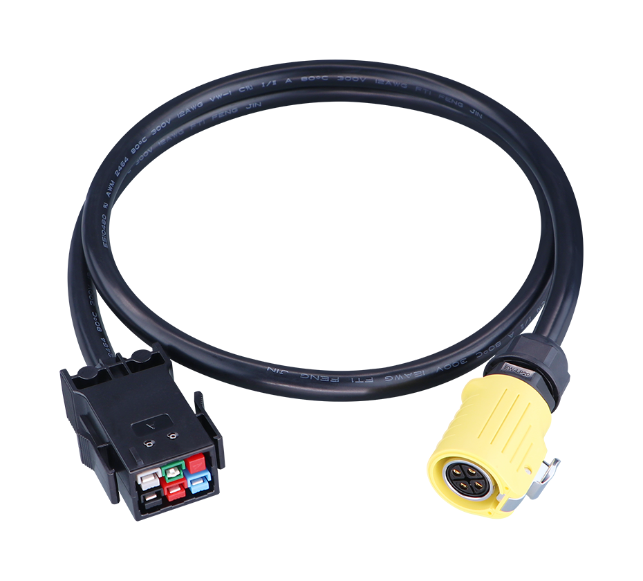
The physical form factor of these connections has evolved in response to the specific demands of micro station deployments. Traditional terminal block connections, while robust, require significant labor to terminate and are prone to errors in field conditions. The industry has increasingly adopted pluggable connector solutions that enable pre-terminated cable assemblies to be quickly and reliably mated in the field, reducing installation time and eliminating the risk of incorrect wiring.
3.2 AC Input Power Plugs: Requirements and Design
The AC input connection of a 5G micro station power system represents the primary interface with the electrical grid. In typical deployments, this connection is made through a standard AC power plug that must satisfy several demanding requirements simultaneously.
First, the connector must provide a safe and reliable electrical connection capable of carrying the full input current of the power system. For a 3,000-watt system operating at 220 volts nominal input, the steady-state current draw approaches 15 amperes, with transient inrush currents potentially reaching significantly higher values during startup. The connector must maintain low contact resistance throughout its service life to minimize voltage drop and heat generation at the contact interface.
Second, the connector must maintain its integrity under environmental exposure. While the power system enclosure itself provides the primary environmental protection, the point at which the AC cable enters the enclosure represents a potential pathway for moisture and contaminants. Cable glands and strain relief mechanisms are typically employed to seal this entry point while providing mechanical support for the cable and preventing stress from being transmitted to the internal connections.
The practical implementation of AC input connections in micro station power systems often employs proprietary or application-specific connector designs rather than standardized plugs. This reflects the specialized nature of the application, where factors such as blind-mating capability, hot-plug safety, and integration with the enclosure’s environmental sealing take precedence over the interchangeability that standardized connectors provide. Some manufacturers have adopted “quick aviation plug” designs that offer tool-free connection and disconnection while maintaining environmental seals.
3.3 DC Output Connections and Load Distribution
The DC output side of a micro station power system presents a more complex connection challenge than the AC input. A typical system must distribute power to multiple loads—radio units, monitoring equipment, and potentially auxiliary devices—each of which may have different voltage and current requirements. Furthermore, the system must accommodate battery connection and charging, which involves bidirectional power flow at currents that can exceed the load current.
Contemporary micro station power supplies typically provide three or more independently protected output branches, each rated for 30 to 40 amperes. Each branch is protected by a fuse or circuit breaker, enabling faults in one load circuit to be isolated without disrupting power to other equipment. This architecture requires a corresponding number of output connectors, each of which must be rated for the full branch current and protected against environmental ingress.
The connectors used for DC output distribution in micro station applications often employ quick-connect terminal designs or pluggable connector systems that facilitate field installation and maintenance. The requirement for “防反插功能” (anti-reverse insertion protection) is frequently specified to prevent damage from incorrect polarity connections during installation or maintenance. This is particularly important in DC systems where reverse polarity can cause immediate and catastrophic damage to sensitive electronic equipment.
Blind-mating capability is another valuable attribute for DC output connectors in micro station applications. When installing or replacing equipment in space-constrained locations—behind a radio unit on a pole, for example—the ability to reliably mate connectors without precise visual alignment simplifies the task and reduces the risk of damaged contacts or incomplete connections.
3.4 Key Technical Specifications
The technical specifications of power plugs and connectors for 5G micro stations must be understood within the context of the complete power system. The following table summarizes the critical parameters that define connector performance requirements:
| Parameter | Typical Specification | Rationale |
|---|---|---|
| AC Input Voltage Range | 85–300 VAC | Accommodates utility voltage variations and brownout conditions |
| AC Input Current | Up to 19 A RMS | For 3,000 W systems at nominal input voltage |
| DC Output Voltage | 43.2–57.6 VDC | Battery charging range for 48 V nominal systems |
| DC Output Current per Branch | 30–40 A | Typical load distribution configuration |
| Operating Temperature | -40 °C to +75 °C | Outdoor deployment extremes |
| Ingress Protection | IP65 | Dust‑tight and water‑jet resistant |
| Insulation Withstand | 3.0 kV AC input‑to‑output | Safety isolation requirement |
| Mechanical Durability | 100–200 mating cycles | Service life with periodic maintenance |
These specifications reflect the demanding operational context of 5G micro station deployments. The wide temperature range, in particular, represents a significant challenge for connector materials. Thermoplastic insulators must remain dimensionally stable and electrically insulating across temperature extremes that would cause many common polymers to become brittle or to soften. Contact materials must maintain low resistance despite thermal cycling and the differential expansion that occurs between dissimilar metals.
3.5 Blind-Mate and Hot-Plug Technologies
Among the technological innovations that have proven particularly valuable for 5G micro station power connections are blind-mate and hot-plug capabilities. These features address the practical realities of field installation and maintenance in challenging environments.
Blind-mate connectors incorporate mechanical features that guide the mating halves into proper alignment even when the installer cannot directly observe the connection point. This capability is typically achieved through the use of guide pins, chamfered lead-ins, or floating contact assemblies that can accommodate a specified range of misalignment. Molex’s PowerWize BMI connectors, for example, provide ±2.00 millimeters of radial self-alignment, allowing reliable mating in drawer-style applications where visual guidance is impossible. The company’s Sentrality series offers ±1.00 millimeter self-alignment with floating capability enabled by wave springs, accommodating tolerance stack-up challenges in board-to-board and busbar-to-board applications.
The mechanical design of blind-mate connectors typically employs guide rails or posts that engage before the electrical contacts, ensuring gross alignment before any electrical connection is attempted. Once aligned, the contact system must provide sufficient compliance to accommodate the residual misalignment without damage to the contacts or degradation of electrical performance. Floating contact designs, where the individual contact elements can move radially within the connector housing, are common approaches to this challenge.
Hot-plug capability, sometimes referred to as hot-swap or hot-mate, enables connectors to be mated and unmated while power is present on one or both sides of the interface. This capability is essential for maintenance operations where power cannot be interrupted, such as in telecommunications systems that must maintain continuous availability. However, hot-plugging presents significant technical challenges: the connector must manage the inrush current that occurs when mating under load, the arc that may form as contacts separate under load, and the thermal transients associated with these events.
Connector manufacturers address hot-plug requirements through several design strategies. The contact geometry may be configured so that the ground connection mates first and breaks last, providing a safe path for fault currents during the mating sequence. Sequenced contacts—where some contacts engage before others—can ensure that power and return paths are established in the correct order. The contact materials and plating must be selected to resist the erosion that can occur from arcing during hot-plug operations.
3.6 Material Considerations for Outdoor Reliability
The materials employed in power plug construction for 5G micro station applications must withstand environmental exposures that would rapidly degrade conventional connector materials. The combination of temperature extremes, humidity, airborne contaminants, and ultraviolet radiation creates a hostile environment for polymers, metals, and platings alike.
Contact materials for high-current applications are typically high-conductivity copper alloys, selected for their combination of electrical performance and mechanical properties. The copper alloy must provide low bulk resistance to minimize voltage drop and heat generation, while also offering sufficient mechanical strength and spring properties to maintain contact force over many mating cycles and thermal excursions. Tellurium copper, beryllium copper, and specialized high-conductivity alloys are common choices.
Plating selection is critical for maintaining low contact resistance and preventing corrosion. Silver plating offers the lowest contact resistance of common plating materials but is susceptible to tarnishing and sulfidation, which can increase resistance over time. Gold plating provides excellent corrosion resistance but at significantly higher cost. Many connectors employ a layered plating scheme, with a thin gold or silver layer over a nickel diffusion barrier, to balance performance and cost considerations.
Housing and insulator materials must provide dielectric strength sufficient to withstand the system’s operating voltage plus transient overvoltages from switching or lightning-induced surges. High-temperature thermoplastics, often glass-reinforced for dimensional stability, are standard for these applications. The material must maintain its mechanical properties across the specified temperature range and must not become brittle or prone to stress cracking when exposed to environmental agents.
Sealing materials—elastomeric gaskets, O-rings, and overmolded seals—determine the connector’s ability to maintain its IP rating over time. Silicone rubber is commonly employed for its wide temperature range and resistance to compression set, which ensures that sealing force is maintained over many years of service. The sealing system must accommodate the dimensional changes that occur with temperature variation while maintaining intimate contact with mating surfaces.
4 Product Ecosystem and Industry Solutions
4.1 Integrated Power Supply Systems
The 5G micro station power supply market has evolved toward integrated systems that combine multiple functions within a single environmentally sealed enclosure. These integrated systems typically incorporate rectification, monitoring, communication, power distribution, and often battery backup within a compact, outdoor-rated package.
Representative products in this category include the EnerSmart 5G Micro Base Station Power Supply from Shenzhen Billey Electrics, which integrates power supply modules (rectifier, monitoring unit, communication unit, and power distribution unit) and lithium battery modules in a modular, digitalized design. This system supports 2,000 or 3,000 watts of output power, operates from a 220-volt single-phase AC input with a wide input range of 170–280 volts, and provides multiple communication interfaces including RS485, CAN, NB-IoT/4G, Bluetooth, and dry contacts.
The integration of battery backup within the power system enclosure reflects the critical importance of uninterrupted power for 5G network availability. The lithium iron phosphate (LFP) batteries commonly employed in these systems offer high energy density, long cycle life, and improved safety characteristics compared to other lithium-ion chemistries. The battery connections within the system—between the battery modules and the power distribution components—represent internal power plugs that must meet the same reliability standards as the external connections.
4.2 Connector Products for Base Station Applications
The connector industry has developed specialized product lines for telecommunications power applications, including solutions specifically targeted at base station and micro station deployments.
Molex’s bus bar connectors, available through distributors such as TTI, are designed for hot-pluggable, high-current applications in telecommunications and high-end computing equipment. These connectors provide blind-mate capability with up to 6 degrees of angular misalignment tolerance and are rated for currents up to 320 amperes. They are dimensionally compatible with competing connectors, enabling drop-in replacement for second-sourcing opportunities.
The PowerPlane Busbar Power Connectors from Molex offer a current range from 130 to 320 amperes with a maximum voltage rating of 600 VAC. These connectors feature a float-mount design accommodating up to ±1 millimeter of misalignment, silver-plated contacts for low resistance, and multiple independent points of contact that increase connection reliability. The operating temperature range of -40°C to +125°C covers the full spectrum of telecommunications deployment environments.
For applications requiring even higher current capacity, Molex’s Sentrality Pin and Socket Interconnects offer ratings up to 350 amperes with pin sizes of 3.40, 6.00, 8.00, and 11.00 millimeters. These connectors incorporate proprietary COEUR socket technology with multiple contact beams that create a large contact surface area, resulting in very low contact resistance and minimal heat generation. The OmniGlide technology provides industry-leading radial self-alignment of up to ±1.00 millimeter, mitigating tolerance stack-up issues in board-to-board and busbar-to-board applications.
TE Connectivity’s CROWN CLIP series, including the CROWN CLIP JUNIOR connector, offers direct bus bar mating capability with a 150-ampere current rating and less than 30°C temperature rise. These connectors feature a unique anti-stress design that allows reliable mating even to misaligned bus bars, addressing one of the persistent challenges in field installation.
4.3 Busbar Connector Solutions
Busbar connectors occupy a distinct position in the 5G micro station power architecture, serving as the interface between power distribution busbars and the equipment they supply. The busbar approach offers several advantages in telecommunications applications: high current capacity in a compact form factor, low resistance and voltage drop, and the ability to distribute power to multiple loads from a single feed point.
Molex’s busbar connector product line includes both the standard Bus Bar Connectors and the PowerWize BMI series. The standard bus bar connectors are designed for direct mating of two perpendicular power bus bars and operate up to 32 amperes rated current, offering over 20 percent more current than competing products. The top entry of the connector mates with a standard 25.40 millimeter wide by 3.18 millimeter thick bus bar tab, facilitating compatibility with common power supply output configurations.
The PowerWize BMI connectors extend this capability to higher currents, with three sizes rated at 75, 110, and 185 amperes. These connectors incorporate the COEUR socket technology for low contact resistance and are available with screw-mount headers that can attach to either printed circuit boards or busbars. The panel-mount receptacle housing features guide posts that align with the header sidewalls before the electrical contacts engage, providing reliable blind-mating in visually obscured spaces.
The application of busbar connectors in 5G micro stations extends beyond the power supply itself to the equipment being powered. Radio units often incorporate busbar connections for their power input, enabling the use of short busbar runs within equipment racks or cabinets. The separable nature of busbar connectors, compared to hard-wired terminal blocks, simplifies equipment replacement and reduces downtime during maintenance operations.
4.4 Industry Standards and Certifications
The 5G micro station power plug ecosystem operates within a framework of industry standards and certifications that ensure interoperability, safety, and reliability. While a comprehensive review of applicable standards is beyond the scope of this analysis, several key documents and requirements merit attention.
In China, which represents a significant portion of global 5G infrastructure deployment, the telecommunications industry standards (YD/T series) provide the primary technical framework. Relevant standards include YD/T 1058-2015 (High-frequency switching power supply systems for telecommunications), YD/T 731-2008 (High-frequency switching rectifiers for telecommunications), and YD/T 944-2007 (Lightning protection technical requirements and testing methods for communication power systems). These standards specify requirements for electrical performance, environmental protection, safety, and electromagnetic compatibility that power supply systems—and by extension, their connectors—must satisfy.
The T/CMEEEA 262-2026 standard, “Design specification for uninterrupted power supply systems of 5G communication base stations,” published by the China Electrical Equipment Engineering Association, provides comprehensive requirements for the design principles, system architecture, equipment configuration, technical requirements, safety protection, energy conservation and environmental protection, and intelligent operation and maintenance of 5G base station power systems. This standard applies to new construction, renovation, and expansion of 5G macro base stations, micro base stations, and indoor distribution systems.
At the international level, the ETSI ES 203 700 standard addresses power supply solutions for 5G networks, including requirements for both -48 V DC and up to 400 V DC power distribution architectures. This standard recognizes the evolving power requirements of 5G equipment and provides guidance for power system design that accommodates multiple energy inputs, lithium battery integration, and digital intelligent management.
Environmental protection standards, particularly those relating to ingress protection (IP codes defined in IEC 60529 and GB/T 4208), are fundamental to outdoor power equipment. The IP65 rating commonly specified for micro station power systems represents a balance between protection and practicality—sufficient to withstand exposure to dust and water spray in outdoor environments without requiring the complete sealing that would make the equipment difficult to service.
4.5 Interface Standards and Interoperability
A persistent challenge in the 5G micro station power plug domain is the relative absence of standardized, interoperable connector interfaces. Unlike consumer electronics, where USB and similar standards ensure interchangeability across manufacturers, the power connectors used in telecommunications infrastructure are often proprietary or application-specific.
This lack of standardization reflects several factors. The specialized requirements of the application—high current, outdoor environmental protection, blind-mating capability—have driven manufacturers toward custom solutions optimized for their specific system architectures. The relatively low production volumes of any single micro station model, compared to consumer products, make the investment in standardized connector development difficult to justify economically. And the conservative nature of telecommunications infrastructure procurement, where proven reliability takes precedence over innovation, favors established designs over new standards.
The consequences of this fragmentation are most apparent in field operations. Maintenance technicians must stock multiple connector types to service equipment from different vendors. The lack of hot-swap interoperability between vendors’ equipment limits the flexibility to replace failed units with available spares. And the inability to source replacement connectors from multiple suppliers creates supply chain vulnerabilities.
Some progress toward interoperability is evident in the dimensionally compatible designs offered by major connector manufacturers. Molex’s bus bar connectors and PowerPlane connectors, for example, are explicitly designed to be dimensionally compatible with competing products, enabling drop-in replacement and second-sourcing opportunities. This approach to compatibility recognizes the practical needs of system integrators while acknowledging that full standardization may be impractical.
5 Installation, Maintenance, and Reliability Considerations
5.1 Installation Practices and Challenges
The installation of power plugs in 5G micro station deployments presents challenges that differ substantially from those encountered in controlled environments such as data centers or central offices. Field installation occurs in conditions that are often less than ideal: inclement weather, limited access, constrained working space, and time pressure to complete the installation and restore or initiate service.
The physical accessibility of connection points varies dramatically with the mounting configuration. Wall-mounted power systems may be installed at heights requiring ladders or lifts, with the connections located on the bottom or side of the enclosure where they are difficult to see and reach. Pole-mounted systems present similar challenges, often compounded by the need to work around the pole itself. Tower-mounted equipment may require climbing and working at heights where every action must be deliberate and efficient.
The use of pluggable connectors significantly eases these challenges compared to traditional terminal block connections. Pre-terminated cable assemblies can be manufactured and tested in controlled factory conditions, ensuring proper wire preparation, correct conductor insertion, and appropriate torque on terminal screws—all of which are difficult to verify in field conditions. The installer need only mate the plug to the receptacle, a task that can be accomplished quickly and with minimal risk of error.
The blind-mate capability of many modern connector designs provides particular value in constrained access situations. When the connection point cannot be directly observed, the ability to mate connectors by feel—with mechanical guidance ensuring proper alignment—enables reliable connections that would be impossible with visual-only mating systems. The self-alignment capabilities of connectors such as Molex’s PowerWize BMI (up to ±2.00 millimeters) and Sentrality (up to ±1.00 millimeter) accommodate the misalignments that inevitably occur in field installations.
5.2 Maintenance and Serviceability
The maintenance requirements of 5G micro station power systems and their connectors reflect the broader operational context of telecommunications infrastructure. With thousands of micro stations deployed across a network, the cost of routine maintenance visits can quickly exceed the capital cost of the equipment itself. The design philosophy for these systems therefore emphasizes “install and forget” operation, with maintenance interventions minimized and, when necessary, achievable without specialized tools or extensive training.
Connector designs that support hot-plug replacement contribute significantly to serviceability. When a power system or radio unit fails, the ability to disconnect and reconnect power without de-energizing the entire circuit reduces the scope of the maintenance operation and limits disruption to other services. Hot-plug capable connectors, such as those in the Molex bus bar and PowerWize series, enable this service mode by managing the arcing and inrush current that would otherwise damage contacts during live mating and unmating.
The mechanical durability of connectors is specified in terms of mating cycles—the number of times the connector can be mated and unmated while maintaining its performance specifications. Typical specifications for telecommunications-grade connectors range from 100 to 200 cycles, which may seem modest but is appropriate for an application where connectors are rarely disturbed after initial installation. The durability specification ensures that the connectors will survive the installation process (which may involve trial fits and adjustments) and any subsequent maintenance operations without degradation.
Condition monitoring of connector performance is not generally practical in deployed micro station systems, but the monitoring systems integrated with modern power supplies can provide indirect indications of connection problems. Voltage measurements at the load terminals, for example, can reveal excessive voltage drop that might indicate high contact resistance at a connector. Current measurements can detect abnormal distribution among parallel load branches. Temperature sensors, where present, can identify localized heating that might result from a degraded connection.
5.3 Reliability Engineering and Failure Modes
The reliability of power plug connections in 5G micro stations is determined by a complex interplay of design factors, material properties, and environmental conditions. Understanding the potential failure modes is essential to designing connectors that achieve the required operational lifetimes.
Contact resistance increase is among the most common failure modes for power connectors. This can result from several mechanisms: oxidation or corrosion of contact surfaces, loss of contact force due to stress relaxation in spring elements, contamination of contact interfaces, or mechanical wear from repeated mating cycles. In outdoor environments, the presence of moisture, airborne contaminants, and temperature cycling accelerates these degradation processes.
The thermal environment to which the connector is exposed is a critical determinant of its reliability. Temperature cycling causes repeated expansion and contraction of materials with different coefficients of thermal expansion, potentially leading to mechanical fatigue or loss of sealing integrity. Elevated temperatures accelerate chemical degradation processes, including oxidation and stress relaxation. The temperature rise at the contact interface itself—resulting from the resistance of the contact and the current flowing through it—adds to the ambient temperature and can create localized hot spots that accelerate degradation.
Environmental sealing failure represents another significant reliability concern. The IP65 rating of the power system enclosure depends in part on the integrity of the seals around cable entries and connector interfaces. Loss of sealing integrity allows moisture and contaminants to enter the enclosure, where they can cause corrosion of internal components, short circuits, or degradation of insulation. Sealing failures can result from improper installation, mechanical damage, or degradation of elastomeric materials over time.
Open circuit failures, while less common than resistance increase, represent a more severe failure mode. These can result from contact fracture, complete loss of contact force, or mechanical failure of the connector housing. The consequences of an open circuit in a micro station power system range from loss of service for the affected equipment to potential damage to other components if the open circuit causes voltage transients or current redistribution.
5.4 Environmental Protection and Testing
The environmental protection requirements for 5G micro station power plugs are verified through standardized testing protocols that simulate the exposures the equipment will experience in service. The IP65 rating, while serving as a useful shorthand for environmental protection, represents the outcome of specific tests rather than a comprehensive characterization of environmental performance.
Ingress protection testing for IP65 involves two separate evaluations. The first digit (6) indicates protection against dust ingress: the equipment is placed in a dust chamber and exposed to a circulating dust atmosphere for a specified duration, after which it must show no evidence of dust penetration. The second digit (5) indicates protection against water jets: the equipment is subjected to water sprayed from a 6.3-millimeter nozzle at a rate of 12.5 liters per minute from all directions, and must show no harmful effects.
Beyond IP testing, telecommunications power equipment is typically subjected to a range of environmental tests that evaluate performance under specific conditions. Temperature cycling tests verify that the equipment can withstand repeated transitions between temperature extremes without mechanical or electrical failure. Humidity testing evaluates resistance to moisture-induced degradation. Salt spray testing, relevant for coastal deployments, assesses resistance to corrosion from airborne salt. Vibration and mechanical shock testing simulates the stresses of transportation and installation.
Lightning protection is a critical concern for outdoor micro station power systems, particularly in regions with high lightning density. The power plugs and connectors must be designed to withstand the transient overvoltages that can couple onto power lines during nearby lightning strikes. Surge protection devices (SPDs) are typically integrated into the power system to divert these transient currents to ground, but the connectors must also be rated for the residual voltages and currents that reach them.
6 Future Trends and Technological Evolution
6.1 Higher Power Density and Efficiency
The trajectory of 5G network evolution points toward continued increases in power density and efficiency requirements for micro station power systems. As radio units become more capable—supporting wider bandwidths, more antenna elements, and more advanced beamforming—their power consumption will correspondingly increase. The power plugs and connectors that deliver this power will need to handle higher currents without increases in physical size.
Higher efficiency is a parallel requirement driven by both operational cost considerations and thermal management constraints. The fanless, sealed enclosure design that enables outdoor deployment depends on minimizing waste heat generation. Every percentage point of efficiency improvement translates directly into reduced thermal load and improved reliability. Connector manufacturers contribute to this goal through contact designs that minimize resistance and thus resistive heating at the connector interface.
6.2 Digitalization and Intelligent Management
The broader trend toward digitalization and intelligent management in telecommunications infrastructure extends to power connectors. While the connectors themselves remain primarily passive electromechanical components, their integration with monitoring systems enables new capabilities for predictive maintenance and operational optimization.
Future connector designs may incorporate embedded sensors for temperature, current, or contact resistance, providing real-time data on connector health and performance. This information could be integrated with the power system’s monitoring and communication functions, enabling remote diagnosis of connector issues before they cause service failures. The data could also inform maintenance scheduling, allowing interventions to be planned when they are most cost-effective rather than on a fixed schedule.
The communication interfaces already present in modern micro station power systems—RS485, CAN, 4G, Bluetooth—provide the infrastructure for transmitting connector health data to network operations centers. The challenge lies in developing connector-integrated sensors that can survive the environmental conditions of outdoor deployment while providing reliable, accurate measurements over the system’s service life.
6.3 Sustainable Materials and Manufacturing
Environmental sustainability considerations are increasingly influencing the design and manufacturing of power connectors and related components. The telecommunications industry, like many others, is under pressure to reduce the environmental footprint of its infrastructure, including the materials used and the manufacturing processes employed.
RoHS (Restriction of Hazardous Substances) compliance is now standard for connectors and other electronic components sold in major markets, restricting the use of lead, mercury, cadmium, and other hazardous materials. Halogen-free materials are increasingly specified for connector housings and insulators, reducing the environmental impact of disposal and the potential for toxic emissions in fire scenarios.
Beyond regulatory compliance, manufacturers are exploring materials with reduced environmental impact throughout their lifecycle. Recycled content in metal components, bio-based polymers for insulators and housings, and manufacturing processes with reduced energy consumption and waste generation are all areas of active development. The challenge is to achieve these sustainability improvements without compromising the performance and reliability that telecommunications applications demand.
6.4 Integration with Edge Computing and IoT
The convergence of 5G communications with edge computing and the Internet of Things (IoT) is creating new requirements for micro station infrastructure. Micro stations increasingly serve not only as communications relays but as edge computing nodes, processing data locally to reduce latency and backhaul requirements. This functional expansion increases both the power requirements and the criticality of reliable power delivery.
The connectors that serve these enhanced micro stations must accommodate the higher power densities and more complex power distribution requirements of edge computing equipment. Multi-voltage outputs—providing, for example, both 48-volt DC for radio equipment and 12-volt DC for computing components—may become more common, requiring connectors that can safely handle multiple voltage levels within a single interface. The monitoring and management capabilities integrated with these connectors will need to provide the granular visibility that edge computing operations require.
The power plugs and connectors that link 5G micro stations to their power sources represent a critical, if often overlooked, component of telecommunications infrastructure. The demands placed on these interfaces—high current capacity in compact form factors, reliable operation across extreme environmental conditions, and ease of installation and maintenance in challenging field situations—have driven significant innovation in connector design and materials.
The evolution of 5G micro station power systems toward integrated, sealed, fanless designs has created a particular set of requirements for the power connections that penetrate the equipment enclosure. The IP65 rating that has become standard for these systems depends on the integrity of every seal and penetration, including those associated with power plugs and
 Yang.taya@aitmpower.com
Tel: 15382891313
Phone: 0769-88878951
Fax: 0769-88878955
Wechat: 15382891313


 CN
 CN
 Home >


