
 2026-10-14
 1
The global deployment of 5G networks represents one of the most significant infrastructure undertakings of the twenty-first century, and at the heart of every base station lies a deceptively simple component: the power connector. While often overlooked in discussions of 5G innovation, power connectors are critical enablers of network reliability, energy efficiency, and long-term operational viability. This article provides a comprehensive examination of 5G base station power connectors, covering the unique electrical and environmental demands of 5G infrastructure, the materials science underpinning high-performance connector design, the mechanical and sealing technologies that ensure decades of outdoor operation, the evolving standards and market dynamics shaping the industry, and the practical selection criteria that engineers must apply when specifying components for macro cell sites, massive MIMO antennas, and small cell deployments.
1. Introduction: The Unseen Backbone of 5G
The fifth generation of mobile telecommunications technology is not merely an incremental improvement over its predecessors. It represents a fundamental rearchitecture of network topology, radio access, and service delivery. Where 4G networks typically deployed a relatively modest number of base stations with moderate power requirements, 5G demands a dramatic densification of infrastructure. Macro sites are being upgraded with Massive MIMO antennas containing 64, 128, or even 256 antenna elements. Small cells are proliferating in urban canyons, stadiums, and transportation hubs to deliver millimeter-wave coverage. And all of this equipment must operate reliably in outdoor environments that subject components to temperature extremes, moisture, vibration, and corrosive atmospheric conditions.
The power connector is the literal and figurative interface between the electrical grid and the radio access network. A failed connector can take an entire sector offline, resulting in dropped calls, lost revenue, and degraded user experience. A connector that operates inefficiently wastes energy and generates heat, compounding thermal management challenges in equipment that is already densely packed and often passively cooled. A connector that corrodes or degrades prematurely imposes maintenance costs that scale linearly with the thousands of sites in a typical national 5G deployment.
Understanding power connectors for 5G base stations therefore requires more than a passing familiarity with connector catalogs. It demands an appreciation of the electrical engineering principles that govern high-current transmission, the materials science that enables both conductivity and mechanical robustness, the mechanical engineering that ensures sealing and strain relief, and the regulatory and standards landscape that defines acceptable performance. This article addresses all of these dimensions, providing a comprehensive reference for engineers, procurement specialists, and technical managers involved in 5G infrastructure deployment.
2. Electrical Requirements: High Current, High Reliability
2.1 Power Demands of 5G Radio Equipment
The power consumption of 5G base station equipment significantly exceeds that of previous generations. A typical 4G remote radio unit (RRU) might draw 10 to 15 amperes from a -48V DC bus. A 5G active antenna unit (AAU) with massive MIMO capability can draw 20 to 30 amperes or more, with some high-power configurations pushing even higher. This increased current draw is a direct consequence of the greater number of antenna elements, the higher processing power required for beamforming and advanced modulation schemes, and the wider bandwidths that 5G operates within.
At the same time, the voltage distribution architecture in many 5G deployments has evolved. While traditional -48V DC systems remain common, especially in existing installations, new high-voltage DC (HVDC) architectures operating at 400V or even 600V DC are being adopted to reduce resistive losses over distribution cables and to enable more efficient power conversion at the point of load. This creates a bifurcated connector market: one segment optimized for low-voltage, high-current applications, and another for high-voltage systems where insulation coordination and creepage distance become critical design parameters.
2.2 Current Rating and Derating
Power connectors for 5G base stations must be rated for continuous operation at currents well above the nominal system load, with a typical derating factor of 1.3 or higher applied to the connector's rated current. This derating accounts for the elevated ambient temperatures that connectors experience in outdoor enclosures, where internal temperatures can reach 80°C or higher under solar loading. A connector rated for 15A at 25°C may only be capable of carrying 10A at 80°C without exceeding its temperature rise limits, which are typically defined by the connector's insulating materials and the maximum permissible temperature of the contact interface.
The contact resistance of the connector is a critical parameter in this context. Even a few milliohms of excess resistance can generate significant heat at 30A: a 5 mΩ contact resistance produces 4.5 watts of waste heat, which must be dissipated through the connector housing and the associated cable. High-quality 5G power connectors achieve contact resistances in the range of 1 to 3 mΩ, often through the use of multi-point contact structures, high-conductivity copper alloys, and precious metal plating at the contact interface.
2.3 Voltage Considerations
For DC power distribution at -48V, the voltage stress on connector insulation is relatively modest. However, the connector must still withstand transient overvoltages that can occur during switching events, lightning-induced surges on the AC side, or fault conditions elsewhere in the power system. A typical 5G power connector might be rated for 300V to 600V working voltage and tested to withstand 2000V to 4000V of dielectric withstanding voltage for one minute.
The situation changes dramatically for HVDC architectures operating at 400V or 600V. At these voltages, the connector must be designed with careful attention to creepage and clearance distances, tracking resistance of insulating materials, and the potential for partial discharge that can degrade insulation over time. The connector housing material must have a high comparative tracking index (CTI) to resist surface tracking under contaminated and humid conditions, and the contact spacing must be sufficient to prevent arcing at the maximum system voltage plus transients.
2.4 Power Quality and Contact Stability
Beyond steady-state current and voltage ratings, 5G power connectors must maintain stable electrical contact under conditions of vibration, thermal cycling, and mechanical shock. A connector that exhibits intermittent contact resistance will produce voltage fluctuations that can disrupt sensitive radio equipment, even if the average current-carrying capability is adequate. This requirement places a premium on contact design: multi-point contacts that distribute the normal force across several independent contact zones, spring-loaded contact elements that maintain force despite thermal expansion and contraction, and locking mechanisms that prevent relative motion between mated halves.
3. Material Science: The Metallurgy of Reliability
3.1 Copper Alloys for High-Conductivity Contacts
The contact elements of a power connector are the components that carry the current and must therefore balance two often-competing requirements: high electrical conductivity to minimize resistive losses, and high mechanical strength and hardness to maintain contact force and resist wear over repeated mating cycles.
Pure copper offers the highest conductivity of any commercially viable metal, at approximately 100% IACS (International Annealed Copper Standard). However, pure copper is soft and lacks the mechanical strength required for reliable contact springs. The solution lies in copper alloys that sacrifice some conductivity for substantial gains in strength and hardness.
The copper-beryllium (Cu-Be) alloys have historically been the gold standard for high-performance connector contacts. With 1.8% to 2.0% beryllium, these alloys achieve tensile strengths exceeding 1200 MPa while retaining 22% to 28% IACS conductivity. They are also highly resistant to stress relaxation, meaning they maintain contact force at elevated temperatures. However, beryllium is toxic, and its use is increasingly restricted by regulations such as the Restriction of Hazardous Substances (RoHS) directive in Europe and similar regulations elsewhere.
The copper-chromium-zirconium (Cu-Cr-Zr) system has emerged as a leading alternative for 5G power connector contacts. These alloys achieve an excellent balance of properties: typical compositions containing 0.5% to 1.3% chromium and 0.1% to 0.25% zirconium can reach tensile strengths of 550 to 650 MPa while maintaining conductivities of 70% to 85% IACS. The chromium and zirconium form fine precipitates during heat treatment that impede dislocation motion and strengthen the alloy, while leaving the copper matrix relatively free of dissolved solutes that would scatter electrons and reduce conductivity.
Recent patent activity has focused on further optimizing Cu-Cr-Zr alloys for 5G applications by adding small amounts of silicon and vanadium. The addition of 0.05% to 0.15% silicon and 0.01% to 0.05% vanadium, combined with controlled homogenization and aging treatments, produces alloys with improved strength and resistance to softening at elevated temperatures—a critical requirement for connectors that must operate reliably at 80°C or above for decades.
3.2 Contact Plating: Gold, Silver, and the Trade-Offs
The base copper alloy of a contact provides the mechanical and electrical foundation, but the contact interface itself is typically plated with a thin layer of a more noble metal. The choice of plating material involves trade-offs among conductivity, corrosion resistance, wear resistance, and cost.
Gold plating is widely used in signal connectors and in power connectors that require the highest reliability and the lowest contact resistance. Gold is essentially immune to oxidation and corrosion under normal atmospheric conditions, and its contact resistance is low and stable. However, gold is expensive, and gold-plated contacts can be sensitive to wear if the plating is too thin or if the contact design produces excessive sliding motion during mating. For power connectors, gold plating thicknesses typically range from 0.5 to 2.0 microns, often over a nickel underplate that provides a diffusion barrier and adds hardness.
Silver plating offers lower contact resistance than gold and is less expensive, but silver is susceptible to tarnishing (sulfidation) in environments containing hydrogen sulfide or other sulfur-bearing compounds. In industrial and urban outdoor environments, this can lead to a gradual increase in contact resistance over time. Silver is therefore more common in connectors that are sealed against atmospheric ingress or in applications where contact resistance is the overriding concern.
Tin plating is the most economical option and is widely used in commercial-grade connectors. Tin is relatively corrosion-resistant under normal conditions, but it forms a thin oxide layer that increases contact resistance. Tin-plated contacts therefore require higher normal forces to break through this oxide layer and establish low-resistance contact, which in turn increases mating forces and wear. For 5G base station power connectors, where reliability and long service life are paramount, tin plating is generally not considered adequate for the main power contacts, though it may be used for secondary or low-current circuits.
3.3 Insulating Materials: Polymers for Harsh Environments
The insulating housing of a power connector serves multiple functions: it mechanically supports the contacts in precise alignment, provides electrical insulation between contacts and between live parts and the user, and protects the contact system from environmental ingress. For 5G base station applications, the housing material must withstand continuous outdoor exposure to ultraviolet radiation, temperature extremes from -40°C to +85°C or higher, humidity, and potentially corrosive atmospheric pollutants.
The material of choice for high-performance outdoor connectors is often a glass-fiber reinforced thermoplastic such as polybutylene terephthalate (PBT) or polyamide (PA). These materials offer an excellent combination of mechanical strength, thermal stability, and resistance to environmental degradation. The UL F1 rating, which is increasingly specified for outdoor connector housings, indicates that the material has been tested and certified for long-term exposure to ultraviolet light and water immersion without significant degradation of mechanical or electrical properties.
For connectors that must meet flammability requirements, the housing material is typically formulated to achieve a UL 94V-0 rating, meaning that it self-extinguishes within 10 seconds after the removal of an ignition source and does not produce flaming drips that could ignite nearby materials. Halogen-free formulations are increasingly preferred for environmental and safety reasons, though achieving both halogen-free composition and V-0 flammability can be challenging.
4. Mechanical Design and Environmental Sealing
4.1 Ingress Protection: IP67, IP68, and Beyond
The Ingress Protection (IP) rating system, defined by IEC 60529, is the standard framework for describing a connector's resistance to dust and water ingress. For 5G base station power connectors, the relevant ratings are almost always in the IP67 or IP68 range.
IP67 indicates that the connector is dust-tight (no dust ingress) and protected against temporary immersion in water up to 1 meter depth for 30 minutes. IP68 indicates protection against continuous immersion under conditions specified by the manufacturer, typically at greater depths and for longer durations than IP67. Many 5G power connectors are rated IP67 in the mated condition, and some achieve IP68 or even IP69K (protection against high-pressure, high-temperature water jets) when mated with appropriate cable assemblies and sealing accessories.
Achieving these ratings requires careful attention to multiple sealing interfaces. The contact cavities must be sealed against moisture ingress, which is typically accomplished through the use of individual wire seals or a grommet that compresses around the cable jacket. The mating interface between plug and receptacle must be sealed with an O-ring or face seal that is compressed when the connector halves are fully engaged. And the cable entry must be sealed with a cable gland or compression nut that grips the cable jacket and prevents water from traveling along the cable into the connector body.
4.2 Locking Mechanisms: Resistance to Vibration and Thermal Cycling
A 5G base station power connector must maintain a reliable mechanical and electrical connection despite the vibration and thermal cycling that characterize outdoor telecommunications environments. Wind loading on tower-mounted equipment produces continuous low-frequency vibration. Thermal cycling from day-night temperature swings and from the equipment's own heat generation causes repeated expansion and contraction of materials with different coefficients of thermal expansion. And in some installations, the connector may be subject to occasional mechanical shock from maintenance activities or nearby construction.
Friction-based locking mechanisms, such as simple push-on connectors, are generally inadequate for these conditions. A positive locking mechanism that produces an audible or tactile confirmation of engagement is essential. Common locking designs include threaded couplings, bayonet (twist-lock) mechanisms, and push-pull designs with internal locking latches.
The threaded coupling is the most robust and is widely used in RF connectors such as the SMA and N-type families. For power connectors, threaded couplings provide high resistance to vibration-induced loosening, but they require more time to mate and may be difficult to engage in tight spaces or with gloves. Bayonet couplings offer faster mating and adequate vibration resistance for many applications, while push-pull designs provide the fastest mating but require careful design of the locking latch to ensure it does not release under vibration.
An additional consideration for 5G power connectors is the potential for hot-plugging—mating or unmating the connector while current is flowing. While hot-plugging is generally discouraged for high-power connectors, the reality of field maintenance means that it occasionally occurs. Connectors intended for 5G applications may incorporate features to suppress or extinguish arcs that form during hot-plug events, such as magnetic arc blowout or sacrificial contact elements that are designed to erode preferentially.
4.3 Strain Relief and Cable Management
The cable attached to a power connector represents a potential point of failure if the mechanical loads on the cable are transmitted directly to the contact terminations. A well-designed connector incorporates strain relief that anchors the cable jacket to the connector housing, so that pulling or bending forces on the cable are absorbed by the strain relief rather than being transmitted to the solder or crimp joints.
For outdoor 5G installations, strain relief must also accommodate the wide temperature range. A strain relief that becomes brittle at -40°C or that softens excessively at +85°C will fail to protect the cable terminations. The materials used for strain relief components—typically elastomers or flexible thermoplastics—must be selected for low-temperature flexibility and high-temperature stability.
Cable management is also a consideration at the system level. Power cables to 5G base stations are often routed through cable trays or conduits and must be protected from abrasion against sharp edges, exposure to UV radiation, and water accumulation at low points. The connector itself may incorporate features such as a bend radius control boot that prevents the cable from being bent too sharply immediately behind the connector, which could damage conductors or insulation.
5. Standards and Certifications
5.1 UL 2238: The North American Standard
Underwriters Laboratories (UL) 2238 is the primary North American safety standard for cable interconnects and connector systems used in signal and power transmission applications. Compliance with UL 2238 demonstrates that a connector has been tested for electrical safety, mechanical reliability, and flame resistance according to recognized procedures. For 5G base station power connectors intended for deployment in North America, UL 2238 certification is typically a customer requirement, even if not mandated by local electrical codes.
The UL 2238 testing regimen includes evaluation of the connector's temperature rise at rated current, dielectric withstanding voltage, insulation resistance, mechanical durability (mating and unmating cycles), and resistance to environmental stresses such as moisture and temperature cycling. Connectors that pass these tests are listed in UL's online database and can be marked with the UL recognized or listed component mark.
5.2 IEC and Regional Standards
At the international level, the International Electrotechnical Commission (IEC) publishes standards that are widely referenced in connector specifications. IEC 61984 covers connectors for use in industrial applications, including requirements for rated voltage, current, temperature rise, and dielectric strength. IEC 60529 defines the IP rating system discussed earlier. And IEC 61076-2-109 specifies the requirements for M12 circular connectors, a format that is sometimes used for power and signal connections in telecommunications equipment.
In Europe, the RoHS directive restricts the use of certain hazardous substances in electrical and electronic equipment, including lead, mercury, cadmium, and hexavalent chromium. Connector manufacturers must ensure that their products comply with RoHS requirements, which may necessitate the use of lead-free solders and alternative plating materials. The REACH regulation on chemicals also affects connector materials, particularly with respect to substances of very high concern (SVHC) that may be present in polymers or plating chemistries.
5.3 Industry-Specific Requirements
Telecommunications equipment manufacturers often impose additional requirements beyond those of general-purpose standards. These may include:
Telcordia GR-326 for optical connectors and GR-1089 for electromagnetic compatibility and lightning protection
IEC 60068 environmental testing procedures, including thermal cycling, damp heat, and salt spray
Customer-specific specifications for mating durability, contact resistance stability, and material compatibility
For 5G deployments specifically, equipment manufacturers may require connectors to operate over an extended temperature range of -40°C to +85°C or higher, to withstand 500 or more mating cycles without degradation of electrical performance, and to maintain IP67 sealing after exposure to thermal shock and vibration.
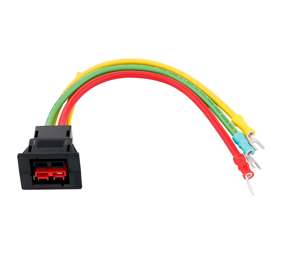
6. Application Scenarios and Selection Criteria
6.1 Macro Base Stations and Massive MIMO AAUs
The most demanding application for 5G power connectors is the power interface to massive MIMO active antenna units. These units integrate dozens or hundreds of antenna elements with their associated radio frequency chains into a single weatherproof enclosure that is mounted on a tower, rooftop, or pole. The power connector must deliver 20A to 30A or more at -48V DC (or higher voltage in HVDC architectures) while occupying minimal space, resisting the full range of outdoor environmental conditions, and maintaining reliable contact through years of vibration and thermal cycling.
In this application, the trend is toward compact, high-current connectors that can be mounted directly on the AAU housing or on a power distribution board within the unit. Connectors with 3.96mm to 7.92mm pitch and current ratings of 15A to 30A per contact are commonly specified. The connectors must be compatible with the potting or conformal coating processes that are often used to protect internal electronics from moisture and contaminants, meaning that the connector housing must allow encapsulant to flow around the contacts without contaminating the contact surfaces.
6.2 Remote Radio Units and Distributed Antenna Systems
Remote radio units (RRUs) represent the workhorse of 4G and early 5G deployments, and they continue to be deployed in 5G networks alongside newer AAU designs. RRU power connectors typically handle 10A to 15A at -48V DC. While the electrical requirements are somewhat less severe than those of massive MIMO AAUs, the environmental requirements are equally demanding, as RRUs are mounted outdoors in a wide range of climates.
For RRU applications, connectors with 3.96mm pitch are often sufficient, such as the SCT3964 series which provides 15A per contact in a compact form factor. These connectors may incorporate features such as positive locking mechanisms, keying to prevent mis-mating, and compatibility with potting processes for enhanced environmental protection.
6.3 Small Cells and Distributed Antenna Systems
Small cells are low-power base stations designed to provide coverage in localized areas such as indoor venues, street furniture, and enterprise campuses. While the power requirements of individual small cells are modest compared to macro sites, the sheer number of small cells in a dense 5G deployment means that connector reliability and cost become significant factors at scale.
Many small cells are powered over Ethernet (PoE), which eliminates the need for a separate power connector but places additional demands on the RJ45 connector to carry both data and power. PoE++ (IEEE 802.3bt) can deliver up to 100W per port, requiring RJ45 connectors with enhanced current-carrying capability and thermal management. For small cells that use separate power connections, compact circular or rectangular connectors with IP67 sealing and 5A to 10A current ratings are typical.
6.4 Selection Checklist for Engineers
When specifying power connectors for 5G base station applications, engineers should consider the following factors:
1. Current and voltage ratings: Determine the maximum continuous current and system voltage, and select a connector with a rated current at least 1.3 times the maximum load and a rated voltage at least equal to the system voltage plus transient margin.
2. Environmental protection: Specify IP67 or IP68 sealing as appropriate for the installation location. Consider UV resistance and the UL F1 rating for exposed outdoor installations.
3. Temperature range: Ensure the connector is rated for the full expected temperature range, typically -40°C to +85°C for outdoor telecommunications equipment.
4. Locking mechanism: Select a positive locking mechanism that provides audible or tactile confirmation of engagement and resists vibration-induced loosening.
5. Mating durability: For connectors that may be unmated during maintenance, specify a mating cycle rating sufficient for the expected service life (typically 50 to 500 cycles for power connectors).
6. Contact material and plating: For high-reliability applications, specify copper alloy contacts with gold or silver plating. Consider the potential for corrosion in the deployment environment.
7. Standards compliance: Verify UL 2238 certification for North American deployments and RoHS compliance for all markets. Check for any customer-specific requirements.
8. Cable compatibility: Ensure the connector accepts the specified cable gauge (AWG) and type, and that the strain relief is appropriate for the cable jacket material and diameter.
7. Market Trends and Future Directions
7.1 Market Growth Driven by 5G Densification
The global market for power connectors is experiencing sustained growth driven in part by 5G infrastructure deployment. Industry analysts project that global 5G infrastructure spending will exceed $70 billion annually by 2027, with Asia-Pacific and North America accounting for the largest shares. The power connector market specifically is expected to grow at a compound annual growth rate of approximately 5% to 7% through the early 2030s, with telecommunications and data center applications representing significant demand drivers.
Within the telecommunications segment, the shift toward higher port densities, higher power levels, and more stringent environmental requirements is favoring connectors with advanced materials and designs. The rectangular connector segment is expected to see the highest growth, driven by its high power density and secure locking mechanisms.
7.2 Material Innovation
The trend toward higher current densities and higher operating temperatures is pushing the limits of conventional copper alloy systems. Research into new alloy compositions, such as the Cu-Cr-Zr-Si-V system described in recent patents, aims to achieve higher strength and softening resistance without sacrificing conductivity. At the same time, the restriction of beryllium in many markets is driving the development of alternative high-performance alloys based on copper-nickel-tin (Cu-Ni-Sn) spinodal alloys and other systems.
On the insulating materials side, the development of halogen-free, high-CTI, flame-retardant polymers is enabling connectors that meet both environmental regulations and the demanding electrical and thermal requirements of 5G applications. Additive manufacturing is also beginning to be explored for connector housings, offering the potential for complex geometries and rapid prototyping of custom designs.
7.3 Integration with Power over Ethernet and Digital Power
The convergence of power and data transmission in a single connector is a growing trend in telecommunications infrastructure. Power over Ethernet is already widely used for small cells and distributed antenna systems, and the latest PoE standards support up to 100W per port. This is driving demand for RJ45 and similar connectors with enhanced current-carrying capability and improved thermal performance.
For higher power levels, digital power management is emerging as a complementary technology. Digital power connectors that integrate sensing and communication capabilities could enable real-time monitoring of connector health, current draw, and temperature, allowing network operators to predict and prevent failures before they occur. While still in early stages, this concept aligns with the broader trend toward intelligent infrastructure in 5G and beyond.
7.4 The Road to 6G
As 5G deployment continues, research into 6G is already underway, with commercial deployments expected around 2030. While the specific requirements of 6G are not yet fully defined, several trends are clear: higher frequencies (sub-terahertz), greater bandwidth, and even denser network architectures. These will translate into continued demands for higher-performance connectors, including higher current densities, wider temperature ranges, and more stringent reliability requirements. The connector industry is already investing in the materials science and mechanical designs that will be needed to support the next generation of wireless infrastructure.
The 5G base station power connector is a component that embodies the intersection of materials science, electrical engineering, and mechanical design. It must carry high currents with minimal loss, maintain reliable contact under vibration and thermal cycling, resist the ingress of water and dust for decades of outdoor service, and comply with a complex web of safety and environmental standards. The copper alloys, plating systems, polymer housings, and sealing technologies that make this possible represent decades of accumulated engineering knowledge and continued refinement.
As 5G networks continue to densify and evolve toward 6G, the demands on power connectors will only increase. Higher power levels, higher operating temperatures, and greater port densities will require continued innovation in materials and designs. The connectors that enable 5G today will be challenged to meet the requirements of the networks of tomorrow. Understanding the principles and practices described in this article provides a foundation for meeting those challenges, ensuring that the unseen backbone of wireless infrastructure remains strong.
 Yang.taya@aitmpower.com
Tel: 15382891313
Phone: 0769-88878951
Fax: 0769-88878955
Wechat: 15382891313


 CN
 CN
 Home >


