
 2026-10-14
 3
Server redundant power connectors are core electromechanical components designed to support the redundant power supply architecture of modern server systems, which are critical to ensuring the continuous, stable and reliable operation of data center servers, enterprise-level storage devices, and high-performance computing equipment. With the rapid development of cloud computing, big data processing, artificial intelligence computing and enterprise informatization construction, servers have become the core carrier of business operation, and the stability of power supply directly determines the uptime of business systems. Redundant power supply systems, realized through matching redundant power connectors, can effectively avoid single-point power failure faults, solve equipment downtime caused by power module damage, line failure or manual maintenance, and achieve 99.999% high availability of server equipment. This paper comprehensively expounds the structural design, working principle, technical specifications, classification standards, application scenarios, installation specifications, failure analysis and daily maintenance of server redundant power connectors, providing systematic technical support for engineering application and equipment management.
The basic concept of server redundant power connectors is derived from the N+1 and N+N redundant power supply design architecture of servers. Traditional single-power server equipment has fatal defects in reliability: once the power supply module fails, the entire server will immediately shut down, resulting in business interruption, data loss and even economic losses. To solve this problem, server manufacturers have widely adopted redundant power supply configurations, that is, configuring two or more independent power supply modules for a single server, and each power module is connected to the server motherboard and power distribution system through an independent redundant power connector. Under normal operating conditions, multiple power modules work in parallel to share the server load; when one of the power modules fails, is powered off or removed for maintenance, the remaining normal power modules can automatically and seamlessly take over the full load power supply, without affecting the continuous operation of the server. The redundant power connector is the key component to realize this switching and parallel power supply function, which needs to meet the technical requirements of high current bearing, low contact resistance, anti-interference, hot plug support and high durability.
In terms of structural design, server redundant power connectors are composed of three core parts: plug terminal, socket base and locking and foolproof mechanism. The plug terminal is connected to the output end of the server power supply module, adopting a multi-pin integrated design, including high-current power supply pins, low-voltage signal pins and grounding pins. The high-current power supply pins are responsible for transmitting the main working voltage of the server, including 12V, 5V, 3.3V and other core voltages required by server chips, hard disks, memory and expansion cards; the low-voltage signal pins are used for power module state detection, current and voltage feedback, fault alarm and hot plug signal transmission; the grounding pins ensure the equipment grounding safety, suppress static electricity and electromagnetic interference, and improve the stability of power signal transmission. The socket base is fixed on the server motherboard or the backplane of the power distribution unit, matching the plug terminal in pin definition and position, and adopting a high-precision stamping and injection molding process to ensure the accuracy and stability of plugging connection.
The locking and foolproof mechanism is a unique key design of server redundant power connectors, which is different from ordinary power connectors. Since the server redundant power supply supports hot plug and replacement in the running state, the connector must have a reliable locking function to prevent loose contact or falling off caused by equipment vibration, air duct ventilation impact and human accidental touch during long-term operation. The locking mechanism is mainly divided into spring snap locking and screw locking. The spring snap locking is widely used in mainstream rack-mounted servers, with the advantages of fast plugging and simple operation; the screw locking is mostly used in high-end industrial servers and key core equipment of data centers, with higher connection firmness and stronger anti-vibration ability. The foolproof mechanism adopts asymmetric pin layout and plastic anti-misplug ribs, which can effectively avoid equipment damage and short-circuit faults caused by reverse plugging or misplugging of power connectors, and improve the safety of equipment operation and maintenance.
In terms of core technical specifications, server redundant power connectors have strict industry standard constraints, mainly including current bearing capacity, voltage resistance grade, contact resistance, plugging life, working temperature and electromagnetic compatibility. The current bearing capacity is the most critical index. According to the server power grade, the conventional redundant power connectors are divided into 800W, 1200W, 1600W, 2000W and above high-current specifications. The single-pin continuous bearing current of high-power models can reach 30A-50A, and the instantaneous peak current can withstand 80A-100A, which meets the instantaneous power demand of server hardware startup and high-load operation. The voltage resistance grade is uniformly designed according to the server DC power supply standard, with a rated working voltage of 0-24V DC and a withstand voltage of 100V DC, which can effectively resist voltage fluctuation and instantaneous surge in the power supply process.
Contact resistance directly affects power transmission efficiency and equipment heat generation. The contact resistance of qualified server redundant power connectors is less than 5mΩ. Too large contact resistance will lead to serious heat generation at the connection position, accelerate the aging of connector metal terminals and plastic insulation layers, and even cause burning and short-circuit faults in severe cases. The plugging life index determines the service life of the connector. Industrial-grade server redundant power connectors have a standard plugging life of more than 1000 times, which fully meets the frequent hot plug and maintenance needs of data center equipment. The working temperature range is -20℃ to +85℃, adapting to the high-temperature and high-density operating environment of server cabinets and data center machine rooms. In terms of electromagnetic compatibility, the connector adopts shielded structural design, which can effectively suppress electromagnetic radiation and anti-external electromagnetic interference, avoid power signal distortion caused by electromagnetic interference, and ensure the stable operation of server high-precision computing chips.
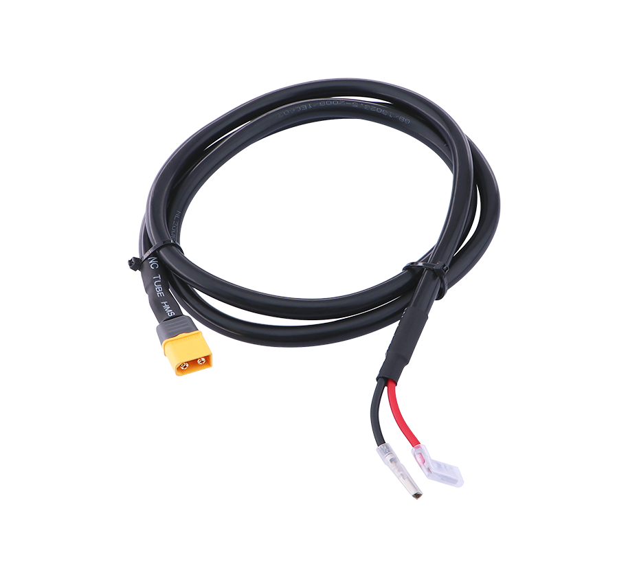
According to industry classification standards, server redundant power connectors can be divided into multiple types according to power specification, structural form and functional characteristics. According to the power supply mode, they are divided into AC redundant power connectors and DC redundant power connectors. AC redundant power connectors are used for server AC input redundant power supply systems, responsible for connecting commercial mains power and server power modules, mostly used in small and medium-sized enterprise servers and edge computing equipment; DC redundant power connectors are used for data center DC power supply systems and server internal power distribution links, with higher current transmission efficiency and stronger stability, which are the mainstream configuration of large cloud data centers and core server clusters.
According to the structural plugging mode, they are divided into vertical plug-in and horizontal plug-in redundant power connectors. Vertical plug-in connectors are vertically installed on the server motherboard, with compact structure and small space occupation, suitable for blade servers and high-density rack servers; horizontal plug-in connectors are horizontally arranged, with convenient plugging and maintenance operation, and are mostly used in tower servers and ordinary rack servers. According to the hot plug function, they can be divided into hot-pluggable and non-hot-pluggable redundant power connectors. Hot-pluggable connectors are the mainstream configuration of modern servers, supporting power module replacement without shutting down the server, which is the core guarantee of server high availability; non-hot-pluggable connectors are only used in low-end entry-level servers, and the power module can only be replaced after shutting down the equipment, with low maintenance efficiency.
The application scenarios of server redundant power connectors cover all high-reliability server application fields, mainly including data center core server clusters, enterprise business servers, industrial control servers, financial transaction servers and communication base station servers. In large-scale cloud data centers, tens of thousands of server devices adopt N+N full redundant power supply configuration, and each server is equipped with two or four redundant power connectors to realize mutual backup of power modules, ensuring that the server will not be shut down due to single power module failure, which is the basic guarantee of cloud service continuity. In the financial industry, transaction servers and core business servers have extremely high requirements for power stability. The redundant power connector system can avoid transaction interruption and data error caused by power failure, ensuring the safety and stability of financial transaction data.
In the industrial control field, industrial servers are deployed in harsh industrial environments such as factories and workshops, with complex power supply environment and many interference factors. Redundant power connectors with anti-vibration, anti-high temperature and anti-interference characteristics can adapt to harsh working conditions and ensure the long-term stable operation of industrial control equipment. In the communication industry, base station servers and core network servers need to operate 24 hours a day without interruption. The redundant power supply system realized by redundant power connectors can effectively resist mains power fluctuation and temporary power failure, ensuring the normal operation of communication network services. In addition, in the fields of medical equipment, aerospace computing and smart city core equipment, server redundant power connectors also play an irreplaceable role in ensuring equipment reliability.
The installation and commissioning specifications of server redundant power connectors are strictly standardized, and non-standard installation will lead to poor contact, power failure and even equipment damage. Before installation, it is necessary to check the integrity of the connector appearance, confirm that there is no damage, deformation, oxidation and dirt on the metal terminals and plastic shell, and verify that the pin definition and power specification of the connector match the server model and power module parameters. During the installation process, the foolproof mechanism must be aligned first, and the plug should be slowly and vertically inserted into the socket base with uniform force, avoiding violent plugging and twisting, so as to prevent the deformation of the metal pins and the damage of the insulation structure. After plugging in, it is necessary to confirm that the locking mechanism is completely clamped, the plug has no loose shaking, and the connection is firm and reliable.
After installation, power-on commissioning and signal detection are required. Use a multimeter to detect the continuity of each power pin and signal pin, check whether the contact resistance is within the standard range, and test the voltage output stability of each power supply channel. At the same time, simulate the single power module failure test, manually disconnect one power module, detect whether the other power module can automatically take over the full load power supply, and verify the effectiveness of the redundant switching function. For hot-pluggable connectors, it is also necessary to conduct multiple hot plug tests to confirm that there is no instantaneous power failure, signal interruption and equipment restart during the plugging process, ensuring that the hot plug function is normal.
In the actual operation process, server redundant power connectors will have various failure problems due to long-term operation, environmental factors and maintenance errors. Common faults include poor contact of pins, loose locking, terminal oxidation and corrosion, plastic shell aging and cracking, and signal pin failure. Poor pin contact is the most frequent fault, mainly caused by long-term vibration, dust accumulation and terminal wear after multiple plugging. The symptom is that the server frequently reports power supply abnormal alarm, the power module is intermittently offline, and the equipment is accidentally shut down in severe cases. Terminal oxidation and corrosion are mostly caused by humid environment in the machine room. The oxidized terminals will increase contact resistance, cause local overheating of the connector, and accelerate the aging of equipment.
Loose locking is caused by the fatigue and failure of the spring locking mechanism. After long-term use, the spring elasticity decreases, resulting in incomplete locking of the connector and loose connection. Plastic shell aging and cracking are caused by long-term high-temperature operation and ultraviolet radiation, which will lead to the deformation of the connector structure and even short-circuit faults caused by the exposure of metal terminals. Signal pin failure will lead to the failure of power module state detection and fault alarm function, making the server unable to identify the working state of the power module, and unable to switch the redundant power supply in time when the module fails, resulting in equipment operation risks.
Daily maintenance and fault maintenance of server redundant power connectors are important links to ensure the long-term stable operation of equipment. Daily maintenance mainly includes regular dust removal, appearance inspection and environmental monitoring. The machine room environment should be kept dry and clean, with the temperature controlled at 18℃-25℃ and the humidity controlled at 40%-60%, to avoid damp oxidation and dust accumulation of connectors. Regularly check the connector connection firmness, observe whether there is discoloration, scorching and deformation at the connection position, and check whether the locking mechanism is flexible and effective. For servers that have been running for more than three years, regular contact resistance detection and pin state inspection are required, and aging connectors should be replaced in time.
For faulty connectors, targeted maintenance and replacement measures should be taken according to the fault type. For slight oxidation and dust pollution of terminals, pure alcohol and anti-static cotton cloth can be used for cleaning, and the operation can be resumed after natural drying. For poor contact caused by spring fatigue and pin wear, the connector assembly needs to be replaced as a whole, and it is forbidden to continue to use defective components. For cracked and aging plastic shells, they should be replaced in time to avoid safety hazards such as short circuit and electric leakage. After fault maintenance and replacement, repeated power-on testing and redundant switching testing are required to ensure that the connector performance meets the standard and the equipment operates normally.
With the continuous upgrading of server technology towards high density, high power and high integration, the technical performance requirements of server redundant power connectors are also constantly improved. In the future, with the popularization of high-power AI servers and high-performance computing servers, the power of single server equipment will continue to increase, and redundant power connectors will develop towards higher current bearing, smaller volume, higher integration and intelligent detection. At the same time, with the improvement of data center energy-saving and environmental protection standards, low-power loss and high-efficiency power transmission will become the important development direction of redundant power connectors, providing more reliable and energy-saving power connection guarantee for next-generation server equipment.
UPS Battery Pack Connectors: Full-Scale Technical Research, Application Standard and Operation Maintenance Guide
UPS (Uninterruptible Power Supply) battery pack connectors are special power connection components used to connect UPS hosts and battery packs, which undertake the core functions of battery power storage, discharge output, charging input and power emergency switching in the UPS power supply system. As the key backup power equipment of data centers, computer rooms, precision instruments, medical equipment and industrial key equipment, UPS systems can effectively solve power supply problems such as mains power failure, voltage surge, voltage drop and power frequency distortion, and ensure the uninterrupted operation of key equipment. The battery pack is the energy storage core of the UPS system, and the UPS battery pack connector is the only channel for energy transmission between the battery pack and the UPS host. Its performance, stability and safety directly determine the emergency power supply capacity, service life and operation safety of the entire UPS system. This paper systematically analyzes the structural characteristics, working principle, technical parameters, classification standards, engineering application specifications, safety management and fault maintenance technology of UPS battery pack connectors, forming a complete technical system for reference in engineering design, equipment selection and operation management.
The working principle of UPS battery pack connectors is based on the energy cycle of UPS charging and discharging. When the mains power supply is normal, the UPS host converts alternating current into direct current through the rectifier module, and transmits the charging current to the battery pack through the battery pack connector to charge the battery and store electric energy; when the mains power is interrupted or the power supply quality is unqualified, the UPS host immediately switches to the battery discharge mode, and the battery pack outputs stable direct current through the connector, which is converted into alternating current by the inverter module of the UPS host to supply power for the load equipment, realizing seamless power supply switching and avoiding equipment shutdown and data loss. In the whole working process, the battery pack connector needs to bear frequent charging and discharging current switching, and maintain stable electrical connection and low-loss power transmission for a long time. At the same time, it needs to have over-current protection, over-temperature protection and anti-spark performance to ensure the safety of battery charging and discharging process.
Different from ordinary power connectors, UPS battery pack connectors have special design requirements in terms of safety performance and dynamic current bearing, because the UPS battery pack has the characteristics of large capacity, high instantaneous discharge current and strong energy storage. In the instantaneous discharge stage of mains power failure, the battery pack needs to output large current in a short time to drive the load equipment to operate stably. The connector must bear the instantaneous impact current without heating and burning; in the long-term floating charging state, the connector needs to maintain stable low-current transmission for a long time, and avoid contact failure and heating aging caused by long-term continuous operation. In addition, the battery pack has the risk of short circuit and overheating failure, so the connector must be equipped with perfect safety protection mechanisms to prevent fire and equipment damage caused by connector failure.
In terms of structural composition, UPS battery pack connectors are composed of four core parts: conductive terminal component, insulating shell, safety protection mechanism and wiring fixing component. The conductive terminal component is the core of power transmission, made of high-purity copper alloy with silver-plated or gold-plated surface treatment. High-purity copper ensures low resistivity and high current transmission efficiency; silver-plated and gold-plated treatments can effectively prevent terminal oxidation, improve corrosion resistance and plugging durability, and maintain long-term stable low contact resistance. The terminal structure adopts a multi-piece elastic contact design, which can ensure sufficient contact area and contact pressure, avoid poor contact caused by vibration and temperature change, and adapt to the dynamic current transmission environment of frequent charging and discharging of UPS batteries.
The insulating shell is made of high-temperature resistant, flame-retardant and impact-resistant engineering plastic materials, which meets the UL94 V-0 flame retardant standard. It has excellent insulation performance, high temperature resistance and anti-aging ability, and can effectively isolate positive and negative electrodes to prevent short-circuit faults. At the same time, the insulating shell is designed with an integrated anti-drop and anti-misplug structure, which can avoid wrong wiring and reverse connection of positive and negative electrodes during installation and maintenance, and greatly improve the operation safety. The safety protection mechanism includes anti-spark contact structure, over-temperature protection groove and locking anti-loosening device. The anti-spark structure can eliminate the electric spark generated during hot plugging of the battery pack, avoid battery arc discharge and fire accidents, and is the key safety design of high-power UPS battery connectors.
The wiring fixing component is divided into crimping type and screw locking type. The crimping type is suitable for small and medium-power UPS battery connectors, with compact structure and convenient wiring; the screw locking type is suitable for high-power industrial UPS battery connectors, with firm wiring, strong current bearing capacity and not easy to loose, which can meet the long-term high-current operation needs of large-capacity battery packs. In addition, high-end UPS battery pack connectors are also equipped with temperature sensing pins and signal detection terminals, which can transmit the temperature and connection state of the connector to the UPS host in real time, realize intelligent monitoring of the battery connection state, and trigger alarm and protection actions in case of abnormal temperature and loose connection.
The core technical parameters of UPS battery pack connectors cover electrical performance, mechanical performance, environmental adaptability and safety standards, which are strictly regulated by international IEC standards and domestic GB industry standards. In terms of electrical performance, the main parameters include rated working current, instantaneous peak current, rated voltage, contact resistance and insulation resistance. The rated working current of mainstream UPS battery connectors ranges from 10A to 200A, which is matched with different power UPS equipment: small office UPS (1KVA-3KVA) is equipped with 10A-30A connectors, medium-sized data center UPS (5KVA-20KVA) is equipped with 50A-100A connectors, and large industrial UPS (above 20KVA) is equipped with 150A-200A high-current connectors. The instantaneous peak current can bear 3-5 times of the rated current, meeting the instantaneous high-current discharge demand of UPS load startup and power failure switching.
The rated voltage of UPS battery pack connectors is mainly 12V, 24V, 48V, 96V and 192V DC, matching the series voltage of different battery packs. The contact resistance is strictly controlled below 3mΩ, which is far lower than that of ordinary power connectors, ensuring low-loss power transmission and avoiding excessive heat generation during high-current operation. The insulation resistance is greater than 1000MΩ, which has excellent insulation performance and can effectively prevent electric leakage and short-circuit faults. In terms of mechanical performance, the standard plugging life is more than 500 times, the locking tension is greater than 50N, and it can resist equipment vibration and external pulling, ensuring the stability of long-term connection.
In terms of environmental adaptability, the working temperature range of UPS battery pack connectors is -40℃ to +105℃, which adapts to the harsh operating environment of outdoor UPS equipment, industrial workshops and low-temperature machine rooms. The humidity resistance level reaches 95% RH non-condensing, which can avoid insulation failure and metal oxidation caused by humid environment. In terms of safety standards, all qualified products must pass UL, CE, RoHS and CCC certification, with flame retardant, anti-explosion and anti-arc performance, and can effectively avoid safety accidents such as fire and explosion caused by connector failure and battery short circuit.
According to different classification dimensions, UPS battery pack connectors can be divided into multiple types to meet the matching needs of different UPS equipment and battery packs. According to power and current specification, they are divided into low-current small-size connectors, medium-current standard connectors and high-current heavy-duty connectors. Low-current small-size connectors are mainly used for household and office small UPS equipment, with small volume, simple structure and convenient installation; medium-current standard connectors are widely used in commercial office buildings, small and medium-sized computer room UPS systems, which are the most widely used universal models; high-current heavy-duty connectors are used for large industrial UPS and data center modular UPS systems, with super current bearing capacity and high safety performance.
According to the structural connection mode, they are divided into plug-in quick-connect connectors and terminal screw fixed connectors. Plug-in quick-connect connectors have the advantages of fast assembly and convenient maintenance, supporting quick disassembly and replacement of battery packs, and are suitable for equipment scenarios requiring frequent battery maintenance and replacement; terminal screw fixed connectors have higher connection firmness and better anti-vibration performance, and are mostly used in fixed industrial UPS equipment and outdoor uninterruptible power supply systems. According to the functional characteristics, they are divided into ordinary conductive connectors and intelligent monitoring connectors. Intelligent monitoring connectors are equipped with temperature detection and state feedback functions, which can realize real-time monitoring of connector temperature, connection state and battery loop state, and greatly improve the intelligent operation and maintenance level of UPS systems.
The application scenarios of UPS battery pack connectors cover all fields requiring uninterruptible power supply guarantee, with wide coverage and strong practicability. In the data center industry, modular UPS systems and high-power industrial UPS systems use high-current intelligent battery pack connectors to realize the series-parallel connection of large-capacity battery packs, ensuring that the server cluster can maintain long-term power supply in case of mains power failure, and providing guarantee for data backup and business continuous operation. In the financial industry, bank core business systems, ATM equipment and securities trading systems rely on high-reliability UPS battery connectors to avoid transaction data errors and business interruption caused by power failure.
In the medical industry, hospital emergency equipment, operating room precision instruments and medical monitoring equipment have zero tolerance for power interruption. The stable connection of UPS battery pack connectors ensures the continuous power supply of medical equipment and guarantees the safety of medical treatment and rescue. In the industrial field, automated production lines, industrial robots and precision detection equipment are equipped with UPS power supply systems. The battery pack connectors can resist industrial vibration and electromagnetic interference, ensure the stable operation of industrial equipment, and avoid production shutdown and economic losses caused by power failure. In addition, in the fields of communication base stations, smart transportation, aerospace equipment and emergency power supply equipment, UPS battery pack connectors play an indispensable core role in power guarantee.
The engineering installation and wiring specifications of UPS battery pack connectors are the key to ensure the safe and stable operation of the system, and non-standard installation is the main cause of connector failure and battery safety accidents. Before installation, professional parameter matching verification must be carried out to confirm that the connector's rated current, rated voltage and interface type are completely consistent with the UPS host and battery pack parameters, and it is forbidden to use connectors with mismatched parameters. At the same time, the appearance of the connector should be inspected to ensure that the shell is intact, the terminals are not oxidized or deformed, and the locking and foolproof mechanisms are flexible and effective. The connecting wire should select the wire diameter matching the connector current specification, and avoid small-diameter wires carrying large current, which will cause wire heating and aging.
During the wiring installation process, the positive and negative electrodes must be strictly distinguished, and reverse connection is strictly prohibited. Reverse connection of the battery pack connector will directly cause UPS host short circuit and equipment burning, and even cause battery explosion and fire accidents. For crimping connectors, professional crimping pliers should be used for crimping operation to ensure that the wire and terminal are tightly crimped without virtual connection and loose connection; for screw locking connectors, the screws should be tightened with a torque wrench according to the standard torque to avoid poor contact caused by insufficient torque and heating failure caused by excessive torque damaging the terminal. After wiring, the insulating sheath should be wrapped completely to avoid exposed terminals causing short-circuit faults.
After the installation is completed, strict power-on detection and function debugging are required. First, use a multimeter to detect the on-off state and insulation performance of the positive and negative loops of the connector to confirm that there is no short circuit and electric leakage. Then conduct charging and discharging tests: test the stability of the battery charging state when the mains power is normal, detect whether the connector is heated abnormally during the charging process; simulate the mains power failure scenario, test the UPS battery discharge switching function, detect the current transmission stability of the connector during high-current discharge, and observe whether there is spark, heating and abnormal noise at the connection position. For intelligent monitoring connectors, it is also necessary to verify the temperature detection and state alarm functions to ensure that the monitoring data is accurate and the alarm response is sensitive.
In the long-term operation process, UPS battery pack connectors are affected by charging and discharging cycle, environmental temperature, humidity and vibration, and various aging and failure problems will occur. Common typical faults include terminal oxidation and corrosion, poor contact heating, locking loosening, shell aging and damage, and monitoring signal failure. Terminal oxidation and corrosion are the most common faults, which are caused by long-term exposure of metal terminals to humid air. Oxidized terminals will increase contact resistance, resulting in obvious heating during battery charging and discharging, accelerating the aging of wires and connectors, and in severe cases, triggering battery thermal runaway and fire accidents.
Poor contact heating is mainly caused by loose wiring, virtual crimping and long-term vibration loosening. Poor contact will lead to local high temperature at the connector, which will melt the insulating shell in severe cases and cause positive and negative short circuit. Locking loosening is caused by long-term plugging and vibration fatigue of the locking mechanism, resulting in unstable connection of the connector, intermittent power failure of the battery loop, and frequent UPS power supply switching faults. Shell aging and damage are caused by long-term high-temperature operation and ultraviolet radiation, leading to shell cracking, insulation performance decline, and easy occurrence of electric leakage and short-circuit faults. Monitoring signal failure of intelligent connectors will lead to inability to monitor battery temperature and connection state in real time, and loss of early warning ability for potential faults, increasing equipment operation risks.
Daily operation and maintenance and fault handling of UPS battery pack connectors are important contents of power system safety management. Daily maintenance should adhere to regular inspection and environmental management. Keep the battery room and equipment environment dry, ventilated and dust-free, control the
 Yang.taya@aitmpower.com
Tel: 15382891313
Phone: 0769-88878951
Fax: 0769-88878955
Wechat: 15382891313


 CN
 CN
 Home >