
 2026-10-14
 3
The modern data center is defined not merely by the computational power of its servers, but by the reliability, efficiency, and manageability of the power infrastructure that sustains them. At the heart of this infrastructure lies the rack-mount power connector ecosystem—a specialized class of interconnect solutions engineered to deliver conditioned electrical energy from facility power sources to the delicate silicon within server chassis. Unlike consumer-grade power connectors, rack-mount power connectors must satisfy a confluence of demanding requirements: high current-carrying capacity within constrained physical envelopes, compatibility with industry-wide standardization frameworks, support for blind-mating and hot-swapping operations, and increasingly, the ability to facilitate intelligent power monitoring and thermal management.
The evolution of rack-mount power connectors mirrors the broader trajectory of data center architecture itself. Early server racks relied upon simple, robust connectors that prioritized mechanical durability over density or intelligence. As compute density increased and rack power budgets escalated from a few kilowatts to tens of kilowatts, connector designs evolved to accommodate higher currents per contact, reduced voltage drop, and improved thermal performance. Today, with the emergence of artificial intelligence and high-performance computing workloads, rack power demands have surged beyond 100 kilowatts in extreme cases, driving innovation in busbar architectures, liquid-cooled power distribution, and connector systems capable of carrying hundreds of amperes per contact.
This comprehensive analysis examines the rack-mount power connector landscape through multiple lenses: the foundational standards that govern interoperability, the architectural approaches to power distribution within the rack, the specific connector families that dominate the market, and the emerging technologies shaping the next generation of power delivery infrastructure. By understanding these elements in concert, data center architects and systems engineers can make informed decisions that balance performance, reliability, and total cost of ownership.
The IEC 60320 Standard and Its Role in Rack Power
Any discussion of rack-mount power connectors must begin with the International Electrotechnical Commission (IEC) 60320 standard, which defines the appliance couplers that serve as the primary interface between power distribution units (PDUs) and IT equipment. The IEC 60320 standard specifies a range of connector types distinguished by current rating, pin configuration, and physical dimensions, with the most relevant for data center applications being the C13/C14 and C19/C20 families .
The C13/C14 pairing represents the ubiquitous workhorse of rack power distribution. The C13 connector, the female cable-end component, mates with the C14 inlet found on the vast majority of servers, switches, and storage arrays. This pairing is rated for 10 amperes internationally, though North American implementations often permit 15 amperes due to regional wiring standards . The C13/C14 interface is deliberately compact, occupying minimal panel space on equipment faceplates—a critical consideration when rack real estate is measured in rack units.
For higher-power equipment, the C19/C20 pairing provides a robust alternative. The C19 connector and C20 inlet are rated for 16 amperes internationally and 20 amperes in North America, with larger contact surfaces and improved thermal characteristics that accommodate the increased current. Blade servers, high-density storage systems, and network core switches frequently employ C19/C20 connections to ensure adequate power delivery without exceeding safe temperature rise limits at the contact interface.
The IEC 60320 standard’s significance extends beyond mere electrical specifications. By establishing a globally recognized interface, it enables a vibrant ecosystem of compatible PDUs, power cords, and equipment inlets from multiple manufacturers. A server designed with a C14 inlet can be confidently deployed in any data center equipped with C13 PDU outlets, regardless of the PDU vendor. This interoperability reduces procurement complexity, simplifies spare parts management, and provides operational flexibility that proprietary connector systems cannot match.
However, the IEC 60320 standard has limitations in the context of modern high-density computing. The maximum current ratings of C13 and C19 connectors—while adequate for traditional rack equipment—become constraints as rack power densities increase. Furthermore, the standard defines only the physical and electrical interface; it does not address hot-swap sequencing, blind-mating tolerances, or signal integration, all of which are essential for contemporary rack architectures. These limitations have driven the development of specialized rack-mount power connectors that extend beyond the IEC 60320 framework.
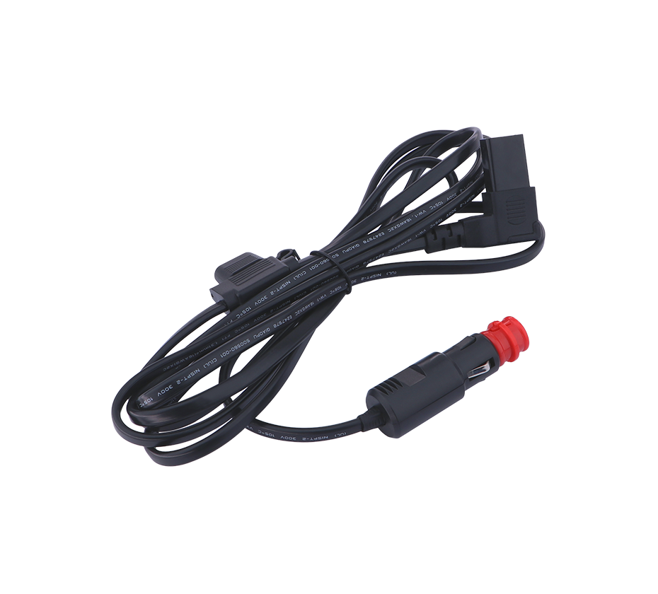
Power Distribution Unit Architecture and Vertical Mounting
The power distribution unit serves as the central node in the rack power topology, receiving input power from facility sources and distributing it to individual equipment via the connector interfaces discussed above. The physical form factor and mounting arrangement of PDUs profoundly influence the connector requirements and the overall cable management strategy within the rack.
Dell’s PowerEdge rack ecosystem provides an instructive example of vertical PDU architecture. Vertical PDUs, which resemble elongated power strips, are designed to mount within the rack’s side channels, occupying zero rack units of valuable front-facing equipment space . This form factor is available in multiple heights: half-height (24U), full-height (42U), and extended-height (48U), corresponding to the internal dimensions of different rack models . The choice of PDU height determines the number of available outlets and the distribution of power capacity along the rack’s vertical axis.
The mounting mechanism for vertical PDUs reflects careful engineering for tool-less installation and serviceability. Standard mounting employs factory-installed pegs that snap into keyhole slots on the rack’s PDU tray, orienting the PDU with its receptacles facing inward toward the equipment . An alternative 90-degree mounting orientation positions the receptacles facing forward, which may be preferred in certain cable routing scenarios but reduces the number of PDUs that can be accommodated per rack due to the space consumed by power cords .
The capacity calculations for vertical PDU deployment reveal the interplay between physical space, connector density, and thermal management. In a Dell 4820 deep rack, for instance, up to eight half-height PDUs can be mounted on a single side in the standard 180-degree orientation, yielding a total of sixteen PDUs across both sides. Full-height and extended-height PDUs, while offering more outlets per unit, reduce the total count due to their greater vertical span . These calculations illustrate a fundamental trade-off in rack power design: greater outlet density per PDU versus the ability to distribute power across multiple, independently monitored strips.
For environments requiring simplified cable management and reduced installation complexity, horizontal PDUs offer an alternative. A 1U horizontal PDU can be mounted in the front or rear of the rack, consuming rack unit space but providing convenient access to outlets and often incorporating additional features such as outlet-level monitoring or switching. The choice between vertical and horizontal PDU form factors depends on factors including rack depth, equipment layout, redundancy requirements, and the desired granularity of power monitoring.
Modular Power Connectors: The MULTI-BEAM Family
While IEC 60320 connectors handle the AC-side interface between PDUs and power supplies, the internal power distribution within server chassis and the DC-side connections to motherboards and components require a different class of connector. The MULTI-BEAM connector family from TE Connectivity represents one of the most widely deployed architectures for these demanding applications, offering a modular, scalable approach to high-current power delivery in rack-mounted systems .
The MULTI-BEAM design philosophy centers on configurability. These connectors combine power contacts and signal contacts within a single housing, enabling a unified interface that carries both high-current power and low-level control signals. The modular construction allows system designers to specify the exact number and arrangement of power and signal contacts required for their application, with mating sequences that ensure ground connections are established before power contacts engage and broken after power contacts disengage—a critical safety feature for hot-swap operations .
Across the MULTI-BEAM portfolio, current-carrying capacity varies to meet different application requirements. The standard MULTI-BEAM XLE connectors support up to 100 amperes per contact with four adjacent power contacts, a rating that has become a benchmark for hot-swappable power supply interfaces . The MULTI-BEAM Plus extends this to 100 amperes per contact while sharing the same low-profile footprint, enabling drop-in upgrades for next-generation power supplies . For the most demanding applications, MULTI-BEAM Pro connectors push the envelope to 185 amperes per individual power contact, achieved through thicker materials and a high-density tail design that improves current-carrying capability without sacrificing the through-system airflow that is essential for thermal management .
The blind-mating capability of MULTI-BEAM connectors is particularly relevant to rack-mount applications. Blind-mate connectors are designed to guide themselves into proper alignment during insertion, compensating for the inevitable misalignments that occur when a power supply or server sled is slid into a chassis. Guide pins and generous lead-in chamfers ensure that mating occurs reliably even when the operator cannot directly observe the connector interface . This feature is indispensable in modern data center operations, where rapid server deployment and hot-swap maintenance are routine requirements.
The thermal management characteristics of MULTI-BEAM connectors reflect the reality that power delivery and cooling are inseparable concerns in dense computing environments. The low-profile design—with height above the printed circuit board as low as 9.6 millimeters in the MULTI-BEAM Lite variant—minimizes obstruction of airflow through the chassis . By maintaining the same profile across successive generations, these connectors enable system designers to upgrade power delivery capability without redesigning the thermal solution. The environmental manufacturing processes used in MULTI-BEAM Lite production further align with the sustainability objectives increasingly emphasized in data center procurement .
Sliding Power Connectors and the Hot-Swap Paradigm
The concept of hot-swapping—replacing components without interrupting system operation—has become foundational to data center reliability and serviceability. Sliding power connectors represent a specialized solution that enables hot-swap capability in server drawers and sleds while eliminating the bulky cable management systems that would otherwise be required .
TE Connectivity’s sliding power connector, one of the few products of its kind, addresses the unique challenges of powering components that slide into and out of a chassis. Traditional cable-based power delivery in such applications requires flexible cable bundles that can accommodate the sliding motion while maintaining electrical connection. These cable systems consume space, obstruct airflow, and introduce failure points where repeated flexing can cause conductor fatigue or insulation damage. The sliding power connector replaces this arrangement with a direct connection between the power source and the server’s on-board components, using printed circuit boards as the power transmission medium .
The technical advantages of this approach are substantial. By eliminating the voltage drop associated with cable assemblies, the sliding connector provides a more direct and efficient power path, improving overall energy efficiency . The simpler design—with fewer loose moving parts and no complex cable management—reduces the risk of disconnection and improves long-term reliability . In applications up to 75 amperes, the sliding power connector delivers these benefits while supporting the hot-swap operations that data center technicians depend upon .
The application space for sliding power connectors includes hard disk drives, power supply units, and the “cubby” modules defined by the Open Compute Project (OCP) for open rack architectures . In each case, the connector enables a drawer or sled to be removed and replaced while the system continues operating, without the need to shut down power to the entire rack. This capability translates directly into reduced downtime costs and improved serviceability—benefits that compound across the thousands of components in a large data center.
Busbar Architecture and High-Current Distribution
As rack power densities increase, the limitations of traditional cable-based distribution become increasingly apparent. Cables require generous bending radii, consume significant space, generate electromagnetic interference, and are labor-intensive to install and route. Busbar architectures address these limitations by replacing discrete cables with solid or laminated conductors that distribute power throughout the rack with greater efficiency, lower cost, and improved thermal performance .
Busbars are typically constructed from aluminum or copper and are designed to transmit high current from a source to multiple loads. The advantages of busbar over cable are multifaceted: busbars offer longer lifespan and more stable operation, eliminate wiring errors through predetermined connection points, require less space due to their compact profile, and dissipate heat more effectively than bundled cables . Installation is faster and less labor-intensive, particularly when busbar systems incorporate hot-pluggable tapping points that allow equipment to be connected or disconnected without tools or downtime .
TE Connectivity’s busbar solutions span rigid, laminated, and flexible configurations, each suited to different rack architectures. Rigid busbars provide high current-carrying capacity with excellent mechanical stability, making them suitable for permanent installations where routing is fixed. Laminated busbars, constructed from multiple layers of conductor and insulation, minimize size while offering low resistance, high capacity, and reduced electromagnetic interference—an important consideration as data rates increase . Flexible busbars accommodate the tolerance stack-ups and movement that occur in sliding drawer applications, providing the electrical performance of busbar with the mechanical compliance of cable .
The integration of busbar with connector systems enables the “smart busbar” concept, in which sensors monitor temperature and other parameters at connection points. By outfitting power connectors and busbars with temperature sensors, operators can gain real-time visibility into the condition of the power distribution infrastructure. This data enables predictive maintenance, allowing repairs to be scheduled before failures occur, and supports dynamic overdriving—operating connectors at higher currents when monitoring confirms that thermal margins remain adequate . The sensors can communicate wirelessly via RF signals or through thermistors, and derive their operating power from the busbar itself, eliminating the need for additional power sources .
The emergence of liquid-cooled busbars represents the next frontier in rack power distribution. As rack-level power requirements continue to escalate, particularly for artificial intelligence and machine learning workloads, busbar capacities must increase accordingly. Liquid cooling of the busbar itself enables higher current capacities while maintaining lower operating temperatures, addressing the thermal challenges that would otherwise limit power density . This approach is particularly relevant for the 48-volt architectures being adopted in OCP Open Rack v3 environments, where power delivery requirements can exceed 500 amperes per rack .
OCP Power Distribution and Open Standards
The Open Compute Project has emerged as a powerful force shaping rack-mount power connector requirements, particularly through its Open Rack specifications. The OCP approach emphasizes standardized, plug-and-play power distribution that can scale from facility power to motherboard applications while maintaining interoperability across vendors .
TE Connectivity’s OCP power distribution solutions illustrate the architecture. The portfolio spans the complete power path: ELCON Micro connectors for facility power interface, MULTI-BEAM Plus connectors for power shelf applications, HDC Lite for battery backup units, and busbar and cable assemblies for distribution throughout the rack . These solutions are designed to comply with Open Rack v3 (ORv3) standards, ensuring compatibility with the 48-volt power distribution architecture that has become central to OCP deployments.
The 48-volt architecture itself is a response to the efficiency and density challenges of conventional 12-volt distribution. By quadrupling the distribution voltage, the current required to deliver a given amount of power is reduced by a factor of four, with corresponding reductions in resistive losses, cable cross-section requirements, and connector contact sizing . The transition to 48 volts has driven new connector requirements, as legacy 12-volt interfaces are not rated for the higher voltages and must be replaced with connectors specifically designed for the higher potential.
OCP’s influence extends beyond electrical specifications to mechanical and thermal design. The Open Rack form factor defines the physical dimensions and mounting arrangements for power shelves, battery backup units, and IT gear, creating a standardized environment in which equipment from multiple vendors can interoperate . This standardization reduces the connector variety required in a data center, simplifying inventory management and reducing the risk of compatibility issues during deployment or maintenance.
The collaboration between connector manufacturers and OCP ecosystem partners has also driven innovation in cooling integration. TE’s immersion cooling proof of concept, developed with Submer and other OCP partners, integrates busbar from TE with immersion cooling technology, demonstrating that power distribution and thermal management can be jointly optimized . Similarly, liquid-cooled vertical busbars developed with partners such as Cooler Master enable higher power distribution in AI-dense racks without increasing busbar footprint .
AC Power Coupling and Rack-Level Infrastructure
The interface between facility AC power and the rack’s internal power infrastructure involves specialized connectors and coupling systems that address safety, modularity, and ease of installation. Detachable power connectivity blocks (PCIBs) represent one approach to modularizing this interface, allowing different input power types—three-phase delta, three-phase wye, or single-phase—to be accommodated through interchangeable wiring blocks that output a universal six-wire configuration .
The PCIB approach separates the concerns of input power configuration from PDU design. The wiring block arranges the incoming power conductors into a standardized output that corresponds to a predetermined terminal configuration in the PDU, regardless of whether the source is three-phase or single-phase . This modularity simplifies design and enables UL-approved field connections without requiring an electrician for each installation, reducing deployment costs and timelines.
The connector interface between the PCIB and the PDU may include additional pins for power ground and input voltage identification. An input voltage identification pin, for example, can signal the PDU when the input is 277 volts rather than a lower voltage, enabling the PDU to automatically disable certain power elements or switchable outlets to protect connected equipment . This intelligence at the connector level enhances safety and prevents misconfiguration that could damage sensitive IT equipment.
At the equipment level, power supply connectors must accommodate the physical constraints of rack-mounted servers. Patent documentation describes connectors with square perimeters and planar facial areas, featuring square arrays of signal pins surrounded by rectangular power pins arranged with ninety-degree rotational symmetry . This symmetry allows the connector to be used in either horizontal or vertical mating orientations, providing flexibility in power supply mounting within the chassis. The tapered tips on both signal and power pins guide the connectors into engagement during blind mating, compensating for the misalignment inherent in sliding power supplies into confined spaces .
High-Density Connectors for Power and Signal Integration
The convergence of power and signal requirements in modern server architectures has driven the development of hybrid connectors that integrate both functions in a single package. This integration reduces connector count, simplifies assembly, and improves reliability by eliminating separate mating operations for power and signal paths.
Amphenol’s CoolPower HD connectors exemplify this trend, offering high-density pin-and-socket designs with current-carrying capabilities of 100 to 250 amperes per pin, depending on pin diameter . The connectors integrate power and signal contacts into a single flexible housing, minimizing board space while optimizing airflow—a critical consideration as component densities increase. The low-profile design and high current density make these connectors suitable for power supply units, battery backup units, and the power distribution shelves that are increasingly common in AI and machine learning server architectures .
Mechanical performance specifications reveal the engineering rigor behind these connectors. CoolPower HD connectors are rated for 250 mating cycles with maximum end-of-life contact resistance of 0.25 milliohms, ensuring reliable operation over the service life of the equipment . The latching mechanisms—pull-to-release for vertical connectors, automatic snap-fit for right-angle versions—provide secure retention while facilitating the tool-less service operations that data center technicians require .
For applications requiring even higher current density, the MULTI-BEAM Pro connectors from TE Connectivity deliver up to 185 amperes per individual power contact with a high-density tail design that carries higher current without increasing the connector footprint . The separated power contacts improve dimensional stability, while the modular design supports custom configurations that match the specific power and signal requirements of each application .
At the lower-power end of the spectrum, the Minitek Pwr PICPWR OCP connector system provides 12-volt auxiliary power distribution for Open Compute Project architectures. Supporting up to 12 amperes per contact in the 2x6 configuration, these connectors distribute power within the HPM (Host Processor Module) and to peripheral subsystems . The 48-volt versions extend the same architecture to higher voltages, supporting the power delivery requirements of next-generation OCP systems . Fully isolated terminals, positive locking mechanisms, and polarized housings prevent mis-mating and ensure secure connections even in high-vibration environments .
Application-Specific Considerations: Storage and Fan Connectors
While the generic requirements for rack-mount power connectors apply across most server components, specific applications introduce specialized demands. Storage connectors, for example, must support both power delivery and high-speed data transmission, often in blind-mate configurations that allow hot-swap disk drives to be inserted and removed without interrupting system operation.
Serial Attached SCSI (SAS) connectors illustrate the integration of power and signal in storage applications. The SAS 3.0 connector supports 12 gigabit-per-second data rates while providing the power necessary to operate high-performance disk drives . Staggered contact lengths enable sequential mating, ensuring that ground and power connections are established before signal contacts engage—a hot-plugging requirement that prevents electrical transients from damaging sensitive electronics . The connector’s molded guideposts help mating halves self-align, compensating for misalignment during blind-mate insertion of drives into carriers .
Fan connectors represent another specialized category. While fans typically consume less power than processors or storage devices, they are essential for thermal management and must be reliable and easily serviceable. Wire-to-board fan connectors with fine pitch (1.25mm, 2.00mm, or 2.54mm) provide compact, cost-effective solutions that support the modularity required for field replacement . Blind-mate fan connectors extend this capability to hot-swap fan modules, allowing cooling components to be replaced without powering down the server.
Material and Performance Considerations
The materials and construction of rack-mount power connectors are dictated by the demanding electrical, thermal, and mechanical requirements of data center environments. High-conductivity copper alloys are standard for power contacts, with silver or gold plating applied to minimize contact resistance and prevent corrosion . The plating material and thickness affect both initial contact resistance and long-term reliability, particularly in environments where temperature cycling and vibration are present.
Housing materials must balance mechanical strength, thermal stability, and flammability requirements. Glass-filled polyamide and other high-performance resins rated to UL94V-0 are common, providing the dimensional stability needed to maintain contact alignment while meeting strict fire safety standards . Halogen-free formulations are increasingly preferred for environmental reasons, particularly in European markets .
Thermal performance is a critical design parameter for high-current connectors. The contact resistance at the connector interface generates heat that must be dissipated to prevent temperature rise that could degrade materials or increase resistance further. Connector designs that maximize contact surface area, improve thermal conduction paths to the printed circuit board, and minimize obstruction of airflow all contribute to better thermal performance . Liquid-cooled busbar solutions represent the most aggressive approach to thermal management, actively removing heat from the power distribution infrastructure to enable higher current densities .
Mechanical durability specifications reflect the operational realities of data center equipment. Mating cycle ratings—250 cycles for CoolPower HD, for example—quantify the connector’s ability to withstand repeated insertion and removal without degradation of electrical or mechanical performance . Minimum wipe length specifications ensure that the contact surfaces slide against each other during mating, breaking through any oxide layers and establishing a clean metal-to-metal interface . These seemingly minor details have outsized effects on long-term reliability.
Emerging Trends and Future Directions
The trajectory of rack-mount power connector development is being shaped by several converging trends that promise to transform data center power infrastructure over the coming decade.
The most immediate pressure comes from escalating power densities. AI and machine learning workloads, with their reliance on high-performance GPUs and specialized accelerators, have pushed rack power requirements from the tens of kilowatts to over 100 kilowatts in the most demanding installations . This increase demands connectors capable of carrying higher currents while maintaining safe operating temperatures. The liquid-cooled busbar, currently emerging from proof-of-concept to early deployment, is likely to become standard in these high-density environments .
The transition to 48-volt distribution architectures, driven by OCP and adopted increasingly by major cloud providers, requires a comprehensive rethinking of connector interfaces. While the higher voltage reduces current requirements for a given power level, it also requires connectors rated for higher potential and designed to prevent accidental contact with live conductors. The OCP power distribution portfolio from TE and similar offerings from other vendors are establishing the connector standards for this transition .
Intelligence at the connector level represents another emerging trend. The smart busbar concept—with embedded temperature sensors that communicate condition data to rack controllers—enables predictive maintenance and dynamic power management . As data center operators seek to optimize efficiency and reliability, the ability to monitor the health of power connections in real time becomes increasingly valuable. Future connectors may integrate additional sensing capabilities, such as current measurement or contact resistance monitoring, to provide even richer data about power distribution system health.
Sustainability considerations are also influencing connector design. The environmental manufacturing processes used in products such as MULTI-BEAM Lite reflect a growing emphasis on reducing the environmental footprint of data center components . RoHS compliance, halogen-free materials, and lead-free manufacturing are becoming baseline requirements rather than differentiators . As data centers face increasing scrutiny over their energy consumption and environmental impact, every component in the power chain—including the connectors—will be evaluated through a sustainability lens.
Rack-mount power connectors constitute a critical but often overlooked element of data center infrastructure. From the ubiquitous IEC 60320 interfaces that connect servers to PDUs, through the modular MULTI-BEAM connectors that deliver DC power within chassis, to the emerging busbar and liquid-cooling solutions that enable the next generation of high-density computing, these components determine the reliability, efficiency, and serviceability of the entire power distribution chain.
The evolution of rack-mount power connectors reflects the broader evolution of data center architecture: from simple, robust interfaces to sophisticated, integrated systems that combine power delivery, signal transmission, thermal management, and intelligent monitoring. The standards that govern these connectors—IEC 60320, OCP Open Rack, and vendor-specific form factors—provide the interoperability that enables multi-vendor data centers, while continuous innovation pushes the boundaries of current density, thermal performance, and operational intelligence.
For data center architects and systems engineers, the implications are clear. Connector selection is not a peripheral concern but a foundational decision that affects power efficiency, cooling requirements, serviceability, and long-term scalability. As rack power densities continue to increase and the complexity of power distribution grows, the connectors that form the links in this chain will play an increasingly visible and consequential role in determining data center performance and reliability.
 Yang.taya@aitmpower.com
Tel: 15382891313
Phone: 0769-88878951
Fax: 0769-88878955
Wechat: 15382891313


 CN
 CN
 Home >