
 2026-10-14
 3
Introduction
Inverter input connectors serve as the critical interface between power sources—whether photovoltaic (PV) arrays, batteries, or AC grid supplies—and the inverter itself. These connectors must reliably transmit electrical power under demanding conditions while maintaining safety, minimizing resistance, and ensuring long-term durability. As inverter technology evolves toward higher voltages, greater power densities, and more sophisticated grid-interactive functionalities, the role of input connectors has become increasingly important. This article provides a comprehensive examination of inverter input connectors, covering DC input configurations, AC input connections, industry standards, selection criteria, and emerging trends.
The Role of Input Connectors in Inverter Systems
An inverter converts direct current (DC) electricity from sources such as solar panels or batteries into alternating current (AC) electricity suitable for household or industrial use. The input side of an inverter typically accommodates DC power from PV strings or battery banks, while the output side delivers AC power to loads or the electrical grid. In hybrid and bidirectional inverters, the same physical terminals may serve as both input and output depending on operational mode.
The input connector's primary functions include establishing a secure electrical connection with minimal contact resistance, maintaining environmental sealing to prevent moisture and dust ingress, providing mechanical strain relief for cables, and enabling safe disconnection under load conditions where required. The overvoltage category on a DC input port is typically classified as II, while the AC output port is rated at category III, reflecting the different transient overvoltage environments these interfaces must withstand.
DC Input Connectors for Photovoltaic Systems
MC4 Connectors
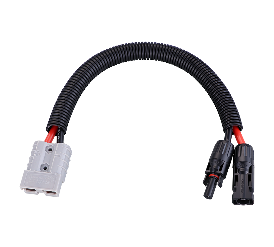
The MC4 connector, developed by Multi-Contact (now Stäubli), has become the de facto standard for PV DC connections worldwide. Its design features a robust locking mechanism that prevents accidental disconnection, with a rated voltage of 1500V DC and current carrying capacity typically up to 30A. The MC4 system comprises a positive and negative connector pair, with each connector consisting of a metal contact pin, a plastic housing, and a sealing gasket. The mating interface employs a snap-in locking mechanism that produces an audible click when properly engaged.
Modern PV inverters commonly ship with MC4 or equivalent connectors pre-installed. For instance, SMA inverters utilize Sunclix DC connectors for certain models, while others employ multicontact MC4 types for battery connections. The connector selection often depends on the specific inverter model and its MPPT (Maximum Power Point Tracking) channel configuration.
Amphenol Helios H4 Connectors
The Amphenol Helios H4 represents an alternative standard that is mechanically compatible with MC4 but differs in certain design details. Huawei's SUN2000 series inverters, for example, ship with either Amphenol Helios H4 or Stäubli MC4 connectors, and the manufacturer explicitly warns that PV connectors of different models cannot be used together. Mixing connector types may result in poor contact, increased resistance, and potential warranty invalidation.
It is important to note that while many generic connectors claim "MC4 compatibility," such connections are often not UL-rated when used in mixed-brand configurations. System designers should always verify that both halves of a connection pair originate from the same manufacturer and carry appropriate certifications.
Terminal Block Connections
Some inverters, particularly larger three-phase models, utilize terminal block connections for DC input rather than plug-in connectors. For example, the Yaskawa Solectria XGI 1500-1MW series specifies 2-hole compression lugs with 1.75-inch spacing for DC input connections, using M10 studs and wiring terminals rated for 90°C conductors. ABB's TRIO series inverters accept DC cables through M25 cable glands, with each terminal accepting a maximum cable cross-section of 16 mm².
Terminal block connections offer advantages in high-current applications where the current exceeds the capacity of standard plug-in connectors. They also provide more secure long-term connections in stationary installations where frequent disconnection is not required.
Input Channel Configurations
The number of DC input channels varies significantly across inverter models. ABB's TRIO-5.8 features a single input channel, while the TRIO-7.5 and TRIO-8.5 each provide two independent channels. Each channel typically corresponds to an independent MPPT tracker, allowing the inverter to optimize power harvest from arrays with different orientations or shading profiles. The correct setting of channels in independent or parallel mode is critical—an incorrect configuration can lead to energy production losses.
AC Input Connectors and Terminal Blocks
For grid-tied and hybrid inverters, the AC input connection enables the inverter to draw power from the grid for battery charging or to synchronize with the grid for net metering. AC input connections typically employ screw-type terminal blocks with clearly marked Line, Neutral, and Ground terminals. Growatt's SPF series, for example, uses two terminal blocks marked "IN" and "OUT," and the manufacturer emphasizes the importance of not mis-connecting input and output circuits.
Cable specifications for AC connections are governed by both current rating and voltage drop considerations. For a typical residential inverter, the recommended cable cross-sectional area ranges from 6.0 to 10.0 mm², with an external diameter of 5.3 to 6.7 mm. If the grid connection distance is excessive, larger-diameter cables should be selected to minimize voltage drop.
The maximum AC input current is typically specified by the inverter manufacturer. For the Deye SUN-6K-G05P1-EU-AM2, the maximum DC input current is 20A, and exceeding this limit may damage the inverter and void the warranty.
Safety and Installation Considerations
Overvoltage Categories
Inverter input connectors must be rated for the appropriate overvoltage category. The DC input port is typically classified as overvoltage category II, while the AC output port is category III. This classification reflects the different transient overvoltage levels that these interfaces may encounter. Category II applies to equipment connected to fixed installations where transient overvoltages are lower, while category III applies to equipment in fixed installations where reliability and availability are subject to special requirements.
Polarity and Connection Integrity
Correct polarity is paramount in DC connections. The positive and negative connectors must be properly matched and inserted into the corresponding inverter terminals. The PV string voltage must not exceed the maximum DC input voltage of the inverter—550V DC for many residential models. Before energizing, the PV resistance to ground should be verified to exceed 20 kΩ to ensure insulation integrity.
Environmental Sealing
Outdoor inverter installations require connectors with appropriate ingress protection ratings. IP65 is the minimum standard for most outdoor PV connectors, while IP67 and IP68 provide higher levels of protection against water immersion. The sealing integrity depends not only on the connector design but also on proper installation—cable glands must be securely tightened, and unused ports must be capped to maintain the rated IP protection level.
Standards and Certifications
IEC 62852 and UL 6703
The primary international standards governing PV connectors are IEC 62852 and UL 6703. IEC 62852 specifies requirements for connectors used in photovoltaic systems, covering electrical performance, mechanical durability, and environmental testing. UL 6703 is the corresponding North American standard, and dual certification is common among major manufacturers. Amphenol's H4 PRO connector, for example, is certified for 1500V DC under both UL 6703 and IEC 62852 standards. TE Connectivity's SOLARLOK connectors are likewise designed for 1500V DC systems and certified to both standards.
Interface Compatibility
The Standard Solar Interface (SSI) design has emerged to promote interoperability between different manufacturers' connectors. However, as noted earlier, cross-brand mating often lacks formal certification even when mechanical compatibility exists. System designers should prioritize using matched connector pairs from a single manufacturer to ensure warranty coverage and reliable performance.
Selection Criteria
When selecting input connectors for an inverter system, several factors must be considered. The voltage rating must exceed the maximum system voltage, typically 1000V or 1500V DC for modern PV systems. The current rating must accommodate the maximum string current with an appropriate safety margin. The ingress protection rating must match the installation environment—IP65 for sheltered outdoor locations and IP68 for areas subject to flooding or frequent washdown. Temperature rating must cover the full expected operating range, typically -40°C to +85°C for standard PV connectors. Finally, certification to relevant standards ensures that the connector has been independently tested for safety and performance.
Future Trends
The inverter input connector landscape continues to evolve in response to several industry trends. Higher system voltages, particularly the transition from 1000V to 1500V DC in utility-scale applications, are driving demand for connectors with enhanced dielectric strength. The growth of energy storage systems is creating demand for connectors that can handle both PV and battery inputs. Miniaturization is enabling more compact inverter designs while maintaining power handling capability. Additionally, the adoption of smart grid technologies may drive integration of monitoring and communication functions into connector assemblies.
Inverter input connectors represent a critical but often overlooked component in power conversion systems. From the ubiquitous MC4 connector to specialized terminal block assemblies, these interfaces must reliably perform under demanding electrical and environmental conditions. Understanding the available connector types, relevant standards, and selection criteria is essential for system designers, installers, and maintenance personnel. As inverter technology continues to advance, input connectors will evolve to meet new challenges in voltage, current, and environmental performance requirements.
 Yang.taya@aitmpower.com
Tel: 15382891313
Phone: 0769-88878951
Fax: 0769-88878955
Wechat: 15382891313


 CN
 CN
 Home >


