
 2026-10-14
 3
Energy storage battery connectors are the electromechanical interfaces that enable the safe, efficient, and maintainable interconnection of battery cells, modules, racks, and power conversion equipment within battery energy storage systems. This article provides a comprehensive technical and market-oriented examination of these connectors, covering their fundamental functions, electrical and mechanical specifications, safety mechanisms, material selection, application segments, installation and maintenance practices, market dynamics, and emerging technology trends. The discussion spans current ratings from tens of amperes to over 600 A, voltage classes up to 1,500 V DC, and applications ranging from residential storage cabinets to utility-scale grid installations. Particular attention is devoted to the design principles that enable reliable operation under high-current, high-voltage conditions, and to the industry trends — including higher power densities, liquid cooling integration, and immersion cooling — that are reshaping connector requirements.
1. The Role of Connectors in Energy Storage Systems
Battery energy storage systems have emerged as foundational infrastructure for modern electricity grids, enabling the temporal decoupling of renewable energy generation from consumption. Whether deployed at the residential, commercial, industrial, or utility scale, every BESS relies on a network of electrical interconnections that must carry substantial DC currents at voltages ranging from several hundred volts to 1,500 V or higher.
Energy storage battery connectors occupy a unique position within this interconnection network. Unlike fixed busbar connections, which are permanent and typically made only during initial assembly, connectors provide a separable interface that facilitates modular assembly, maintenance, and reconfiguration. This separability introduces engineering challenges that do not exist in permanent connections: the contact interface must maintain low electrical resistance across hundreds or even thousands of mating cycles, the sealing system must protect the electrical contacts from environmental ingress while remaining operable, and the locking mechanism must prevent accidental disconnection without making intentional disconnection unnecessarily difficult.
The global market for energy storage battery connectors reflects these technical demands. The market has been estimated at substantial scale and is projected to grow at a compound annual growth rate exceeding 15% through the early 2030s, driven by the accelerating deployment of grid-scale and commercial storage worldwide. This growth is accompanied by a structural shift toward higher current ratings, higher voltage classes, and more sophisticated safety features.
2. Fundamental Functions and Design Requirements
2.1 Electrical Function: Low-Resistance Power Transfer
The primary function of an energy storage battery connector is to transfer electrical power with minimal resistive loss. Contact resistance is the key electrical parameter: every milliohm of resistance in the connector contributes to power dissipation (I²R losses) that generates heat, reduces system efficiency, and accelerates contact degradation.
For a connector carrying 400 A with 0.3 mΩ of contact resistance, the resistive power loss is approximately 48 W. While this may appear modest in isolation, the cumulative losses across dozens of connectors in a large BESS can become significant, and the localized heating at each contact interface must be managed to prevent temperature rise beyond the material limits. UL 4128 certification establishes a temperature rise limit of 45 K at the electrical contact points under rated current, a requirement that effectively constrains the maximum acceptable contact resistance as a function of current rating and thermal design.
2.2 Mechanical Function: Secure and Serviceable Interconnection
The mechanical design of an energy storage connector must satisfy two potentially conflicting objectives: the connection must be secure enough to prevent accidental disconnection under vibration, thermal cycling, and cable movement, yet it must be readily separable by a technician during maintenance or module replacement. This balance is achieved through locking mechanisms that provide tactile and visual confirmation of proper engagement, combined with release mechanisms that can be operated with common tools or, in some designs, by hand.
Mating cycle life is another critical mechanical parameter. Connectors intended for applications where modules are frequently replaced or reconfigured may be rated for hundreds of mating cycles, while connectors in more permanent installations may require only dozens. The contact design — particularly the spring force and the wear resistance of the plating — determines the connector's ability to maintain low contact resistance over its rated cycle life.
2.3 Environmental Function: Sealing and Protection
Energy storage connectors are frequently deployed in environments where moisture, dust, and temperature extremes are present. Outdoor containerized BESS, in particular, expose connectors to rain, condensation, and airborne particulates. The sealing system — typically comprising gaskets, O-rings, and overmolded elastomeric components — must prevent ingress that could compromise insulation resistance or corrode contact surfaces.
The IP67 and IP68 ratings commonly specified for energy storage connectors provide measurable benchmarks for sealing performance. IP67 indicates protection against dust ingress and temporary immersion in water up to 1 meter for 30 minutes, while IP68 denotes protection against continuous immersion under conditions specified by the manufacturer. Achieving these ratings requires careful design of the sealing interfaces, including the plug-to-socket interface, the cable entry point, and any panel-mounting interfaces.
3. Electrical Specifications and Current Ratings
3.1 Voltage Classes
Energy storage connectors are available in several voltage classes, with 1,000 V DC and 1,500 V DC being the most common for modern BESS applications. The trend toward higher voltage is driven by the fundamental relationship between power, voltage, and current: for a given power level, increasing the voltage reduces the current, which in turn reduces resistive losses, cable cross-sectional area, and connector size.
The transition from 1,000 V to 1,500 V DC architectures in energy storage systems has been a significant development. A 1.5 MW battery rack operating at 1,000 V requires 1,500 A of current, whereas the same rack at 1,500 V requires only 1,000 A. This 33% reduction in current translates directly into lower I²R losses in cables and connectors, reduced thermal management burden, and the ability to use smaller, lighter, and less expensive conductors.
3.2 Current Ratings and Product Segmentation
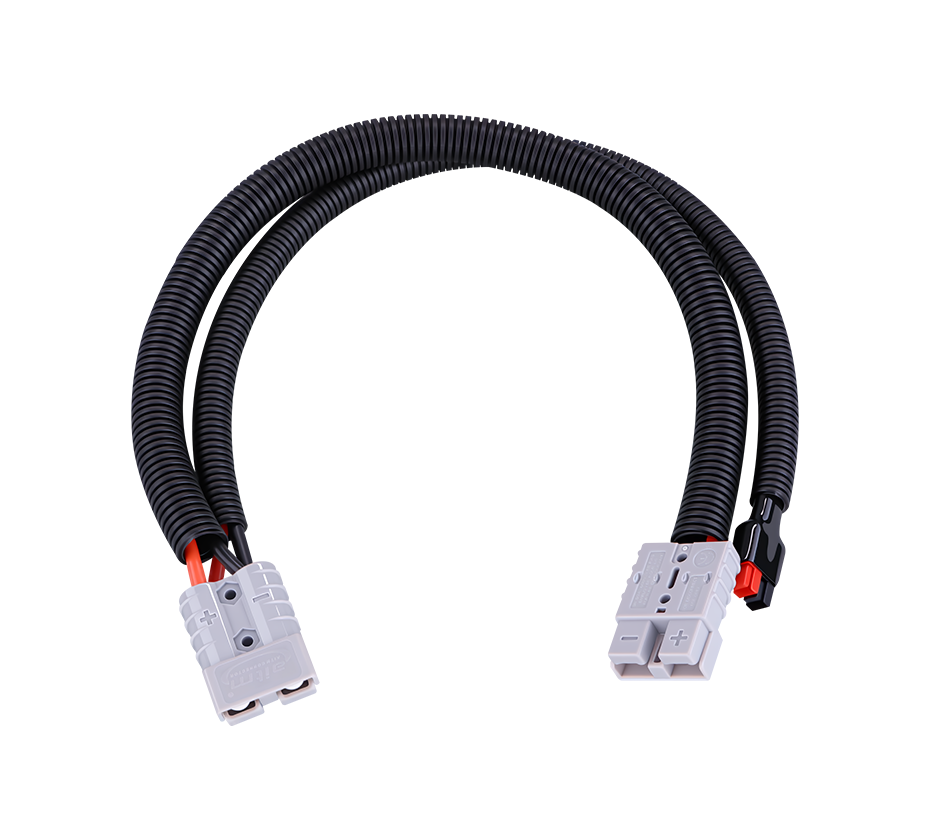
The current rating of energy storage connectors spans a wide range, from approximately 50 A for module-level interconnections to over 600 A for system-level bus connections. This range reflects the hierarchical architecture of BESS installations:
Module-level connectors (50–150 A): These connect individual battery modules within a rack. They typically operate at lower voltages and carry the current produced by a single module or a small group of parallel modules.
Rack-level connectors (150–350 A): These interface battery racks to the DC bus or to power conversion equipment. They must carry the aggregate current of the modules within the rack and are often the most numerous connectors in a large installation.
System-level connectors (350–600+ A): These are used at the interface between the battery system and the power conversion system (PCS), or between major system sections. They carry the highest currents and are subject to the most stringent thermal and mechanical requirements.
The upper end of the current range continues to expand. Connectors rated for 450 A at 1,500 V DC are now commercially available, and products with 500 A ratings have been introduced for high-capacity battery modules. This trend is driven by the increasing capacity of individual battery cells — cells exceeding 500 Ah are now entering the market — which requires higher-current interconnections at the module and rack level.
4. Safety Mechanisms and Design Features
4.1 Arc Prevention and Mitigation
Electrical arcing at connector interfaces represents one of the most serious safety hazards in DC energy storage systems. Unlike AC systems, where the current naturally crosses zero twice per cycle and extinguishes arcs, DC arcs can sustain indefinitely once established, generating intense heat and ionized plasma that can ignite surrounding materials and cause catastrophic damage.
Energy storage connectors address arc risk through multiple design strategies. The primary approach is to ensure that the connector is never mated or unmated under load, as mandated by UL 4128. However, in practical installations, inadvertent load-break operation can occur due to operator error or equipment malfunction. To mitigate this risk, many connectors incorporate features such as:
Sequenced contact engagement: The ground and communication contacts engage before the power contacts, ensuring that any potential difference is equalized before power is transferred.
Arc suppression chambers: Some high-current connectors include internal structures designed to cool and extinguish arcs that may form during accidental disconnection.
Push-to-release mechanisms: Locking systems that require a deliberate, multi-step action to disconnect reduce the likelihood of accidental separation.
4.2 Touch Protection and Finger-Safe Design
The high voltages present in energy storage systems — up to 1,500 V DC or higher — make accidental contact with live conductive parts potentially lethal. Finger-safe design is therefore a mandatory feature of energy storage connectors, ensuring that no live surface is accessible to a standard test finger (as defined in IEC 60529) when the connector is in the unmated condition.
Finger-safe designs typically incorporate recessed contacts within the connector housing, with insulating barriers that prevent insertion of fingers or tools into the contact area. In some designs, the live contacts are completely enclosed even when the connector is disconnected, a feature that significantly reduces the risk of electric shock during maintenance and troubleshooting.
4.3 Color Coding and Mechanical Keying
Reverse polarity connection is a persistent risk in field installations, particularly when multiple similar connectors are present in close proximity. Connecting positive and negative terminals incorrectly can cause immediate short circuits, destroy battery management electronics, and potentially initiate a fire.
Energy storage connectors employ two complementary approaches to prevent polarity errors. Color coding — typically red for positive and black for negative — provides visual differentiation. Mechanical keying provides physical differentiation: the plug and socket geometries are designed so that a positive connector cannot be inserted into a negative inlet and vice versa. Some connectors support multiple keying configurations, allowing different circuits within the same system to use mechanically incompatible connectors, preventing cross-connection between circuits.
4.4 Secondary Locking and Visual Verification
A secure connection requires more than simply inserting the plug into the socket. Vibration, thermal cycling, and cable movement can gradually loosen a connector, increasing contact resistance and creating hot spots. Secondary locking mechanisms provide an additional retention force beyond the primary latch, and visual indicators confirm that the lock is fully engaged.
Some advanced connector designs incorporate a two-stage locking system with clearly marked "Unlocked" and "Fully Locked" positions. The secondary lock can only be engaged when the primary lock is fully seated, ensuring that the operator must complete the full engagement sequence. The visual confirmation feature allows inspectors to verify proper connection without disassembling the joint, a significant advantage in large installations where hundreds of connectors may be present.
5. Materials and Construction
5.1 Housing and Insulation Materials
The housing of an energy storage connector serves multiple functions: it provides mechanical protection for the internal contacts, establishes the creepage and clearance distances necessary for insulation coordination, and incorporates the keying and locking features that define the connector's interface. The material selection for the housing must balance dielectric strength, mechanical toughness, flame retardancy, and cost.
Polyamide 66 (PA66) reinforced with glass fiber is the most widely used housing material for energy storage connectors. PA66 offers excellent mechanical strength and toughness, good dielectric properties, and a high comparative tracking index. When formulated with flame retardants, it can achieve the UL94 V-0 rating required for battery system components. Glass fiber reinforcement (typically 20–30% by weight) increases stiffness and dimensional stability while reducing the coefficient of thermal expansion.
5.2 Contact Materials and Plating
The electrical contacts are the functional heart of the connector. They must provide low and stable contact resistance over the connector's life, resist wear from repeated mating and unmating, and withstand the thermal stresses of continuous current flow.
Copper alloys — particularly those containing beryllium, tellurium, or chromium — are the standard base materials for energy storage connector contacts. These alloys combine high electrical conductivity with sufficient mechanical strength and spring properties to maintain contact force over many mating cycles. The contact surfaces are typically plated with silver, which offers low contact resistance, good wear resistance, and resistance to oxidation. Gold plating may be specified for applications requiring extremely low and stable contact resistance, though the cost differential limits its use to specialized applications.
5.3 Sealing Materials
The elastomeric components — gaskets, O-rings, and overmolded seals — are critical to the connector's environmental protection. These materials must maintain their sealing force and elasticity over the connector's rated temperature range, resist compression set (the tendency to lose sealing force under sustained compression), and withstand exposure to the environmental conditions present in the installation.
Silicone rubber and fluoroelastomer (FKM, commonly known as Viton) are the most common sealing materials. Silicone offers excellent low-temperature flexibility and good high-temperature resistance, while FKM provides superior resistance to oils, fuels, and chemicals. The UL 4128 accelerated aging test — 70 hours at 100°C with a hardness change limit of 10 durometer units — establishes a minimum performance benchmark that sealing materials must meet.
6. Application Segments and Installation Practices
6.1 Residential Energy Storage
Residential BESS installations typically involve a single battery cabinet or a small number of modules connected to a hybrid inverter. Connectors in these systems are rated for lower currents (typically 50–150 A) and are often installed in protected indoor environments, though outdoor installations are increasingly common.
The key requirements for residential connectors are ease of installation (since these systems are often installed by electricians rather than specialized battery technicians), compact dimensions (to fit within limited cabinet space), and reliable sealing for outdoor-rated enclosures. Tool-free or minimal-tool installation is a significant advantage in this segment.
6.2 Commercial and Industrial Energy Storage
Commercial and industrial (C&I) storage systems are typically containerized or cabinet-based installations ranging from 100 kWh to several megawatt-hours. These systems often operate in outdoor or semi-outdoor environments and must maintain reliability across a wide temperature range.
Connectors for C&I applications are rated for currents of 200–450 A and must provide robust sealing (IP67 or better) to withstand outdoor exposure. The modular architecture of C&I systems means that connectors are frequently mated and unmated during system expansion or module replacement, placing a premium on mating cycle life and ease of field servicing.
6.3 Utility-Scale Grid Storage
Utility-scale BESS installations can exceed 100 MWh and involve thousands of individual connectors distributed across hundreds of battery racks. The sheer scale of these installations amplifies the consequences of connector failures: a single connector that develops excessive contact resistance can create a hot spot that, if undetected, may escalate to a thermal event with system-wide consequences.
Connectors for utility-scale applications are rated at the high end of the current spectrum (350–600+ A) and are designed for the most demanding thermal and mechanical conditions. The ability to verify proper installation through visual indicators and the availability of connector temperature monitoring (using integrated sensors) are increasingly specified by utility customers.
6.4 Specialized Applications
Beyond the conventional residential, C&I, and utility segments, energy storage connectors are increasingly employed in specialized applications including:
Mobile BESS: Containerized storage systems mounted on trailers or trucks for temporary power or disaster relief. These applications demand connectors that can withstand transportation vibration and rapid deployment.
Data center backup storage: Connectors in data center applications must meet the same reliability standards as IT power infrastructure, with additional requirements for minimal downtime during maintenance.
Electric vehicle charging with storage: Storage-assisted charging stations use battery connectors to buffer grid power and deliver high-current charging to vehicles.
7. Market Dynamics and Growth Drivers
7.1 Market Size and Growth Trajectory
The global energy storage battery connector market is experiencing rapid expansion, driven by the unprecedented deployment of battery storage capacity worldwide. Market research indicates that the global energy storage high-voltage connector market was valued at approximately USD 279 million in 2025, with projections reaching USD 351 million by 2032. More broadly, the energy storage battery connector market has been forecast to reach USD 1,616 million by 2031, growing at a compound annual growth rate of 15.3% from 2024.
This growth is not evenly distributed geographically. The Asia-Pacific region currently represents the largest market for energy storage connectors, reflecting the concentration of battery manufacturing and BESS deployment in China, South Korea, and Japan. However, North America and Europe are expected to exhibit faster growth rates as utility-scale storage deployments accelerate in response to renewable portfolio standards, grid reliability requirements, and decarbonization mandates.
7.2 Key Growth Drivers
Several structural factors are driving connector demand growth that outpaces the underlying growth in energy storage capacity:
Higher connector density per MWh: As battery modules become more energy-dense and racks more tightly packed, the number of connectors per unit of storage capacity is increasing. Each module-to-rack connection, rack-to-bus connection, and bus-to-PCS connection requires a dedicated connector pair.
Higher current ratings per connector: The shift toward larger battery cells (500+ Ah) and higher-voltage architectures (1,500 V DC) is driving demand for connectors with higher current ratings and more sophisticated thermal management features.
Replacement and aftermarket demand: Connectors have a finite mating cycle life and are subject to wear and environmental degradation. The installed base of energy storage systems is now large enough that replacement connector demand is becoming a meaningful market segment.
Certification requirements: The increasing stringency of safety certification requirements, particularly in North America and Europe, is driving demand for higher-quality, certified connectors even in price-sensitive market segments where uncertified alternatives were previously accepted.
7.3 Competitive Landscape
The energy storage connector market is served by a diverse set of suppliers ranging from large, diversified connector manufacturers to specialized energy storage connector companies. Major international players include TE Connectivity, Amphenol, Harting, Phoenix Contact, Molex, and Stäubli, each offering product lines tailored to different segments of the energy storage market. Chinese manufacturers such as DEGSON, Yonggui, and others have also established significant positions, particularly in the Asian market and in cost-sensitive applications.
Competitive differentiation in this market is increasingly based on factors beyond basic electrical specifications. Certification coverage (UL, TUV, CE), mating cycle life, sealing performance, thermal management capabilities, and the availability of application engineering support are all important selection criteria for BESS integrators.
8. Emerging Technology Trends
8.1 Higher Current Ratings and Busbar Connections
The demand for higher current capacity is driving connector designs toward larger contact geometries and alternative termination methods. Flexible busbar connectors, which replace traditional cable terminations with laminated copper busbars, offer lower resistance, better heat dissipation, and more compact dimensions for high-current applications. These connectors support current ratings up to 600 A and are increasingly specified for module-to-rack and rack-to-bus connections in utility-scale systems.
8.2 Liquid Cooling Integration
As energy storage systems transition to liquid-cooled thermal management — a shift driven by the higher power densities of modern battery cells — connectors must interface with cooling circuits as well as electrical circuits. Some advanced connector designs incorporate integrated fluid channels, allowing coolant to flow through the connector body to extract heat directly from the contact area. This approach enables higher current ratings within the same connector envelope and extends contact life by reducing operating temperatures.
8.3 Immersion Cooling Compatibility
Immersion cooling, in which battery modules and connectors are fully submerged in a dielectric fluid, represents the most aggressive thermal management approach for high-density energy storage. Connectors designed for immersion cooling must maintain their electrical and sealing performance when continuously exposed to the coolant fluid. This requires careful selection of materials that are compatible with the coolant chemistry and verification that the connector's sealing system prevents coolant from reaching the contact interface, where it could cause corrosion or insulation degradation.
8.4 Integrated Sensing and Monitoring
The integration of temperature and current sensors into energy storage connectors is an emerging trend that addresses the need for continuous monitoring of connector health in large installations. Temperature sensors embedded near the contact interface can detect the early stages of contact degradation — an increase in contact resistance produces a measurable temperature rise that precedes more serious failure. Some connector designs now offer optional integrated temperature sensors that can be connected to the BESS monitoring system.
9. Installation, Maintenance, and Best Practices
9.1 Installation Considerations
Proper installation is essential to achieving the rated performance and reliability of energy storage connectors. Key installation practices include:
Verifying compatibility: Before mating, confirm that the plug and socket are compatible in terms of current rating, voltage rating, keying configuration, and sealing requirements.
Inspecting for damage: Examine the connector housing, contacts, and seals for signs of damage or contamination before installation. Damaged connectors should never be installed.
Ensuring proper alignment: Insert the plug straight into the socket without twisting or forcing. Most connectors are designed for straight-line insertion; angular insertion can damage the contacts or the sealing surfaces.
Confirming full engagement: Verify that the locking mechanism is fully engaged and that any visual indicators confirm proper connection. A partially engaged connector can have elevated contact resistance and is at risk of disconnection under vibration.
9.2 Maintenance and Inspection
Routine inspection of energy storage connectors should include visual examination for signs of overheating (discoloration, melting, or deformation), corrosion, or seal degradation. In systems equipped with temperature monitoring, trend analysis of contact temperatures can identify connectors that are beginning to degrade before visible signs appear.
When connectors are unmated for maintenance, both the plug and socket should be inspected for wear or contamination. Contacts that show signs of pitting, discoloration, or excessive wear should be replaced. Sealing surfaces should be cleaned and, if necessary, the seals replaced before remating.
9.3 End-of-Life Considerations
Energy storage connectors have a finite service life determined by mating cycles, thermal exposure, and environmental conditions. At the end of their rated life, connectors should be replaced rather than reused, even if they appear visually intact. The degradation of contact plating, sealing elastomers, and housing materials may not be visible but can significantly compromise performance and safety.
Energy storage battery connectors are critical enablers of the global energy transition, providing the separable electrical interfaces that make modular, maintainable battery storage systems possible. Their design and construction reflect a careful balance of electrical performance, thermal management, mechanical robustness, and environmental protection. As energy storage systems evolve toward higher voltages, higher currents, and more demanding operating environments, connector technology continues to advance in response. The integration of liquid cooling, immersion compatibility, and embedded sensing represents the current frontier of connector innovation. For system designers and integrators, the selection of appropriate connectors — matched to the electrical, thermal, and environmental requirements of each application — is a foundational decision that directly influences system safety, reliability, and total cost of ownership.
 Yang.taya@aitmpower.com
Tel: 15382891313
Phone: 0769-88878951
Fax: 0769-88878955
Wechat: 15382891313


 CN
 CN
 Home >


