
 2026-10-14
 2
1. Introduction: The Role of Quick-Connect Connectors in UPS Systems
Uninterruptible power supplies (UPS) form the backbone of power reliability in data centers, bridging the gap between utility power and critical IT loads during outages, voltage sags, and frequency variations. The effectiveness of a UPS system depends not only on its internal electronics and battery capacity but also on the integrity and reliability of its external connections. A UPS that performs flawlessly in the laboratory but suffers from a loose input connection or a degraded output interface will fail when it matters most.
Quick-connect connectors play a central role in UPS installations. They provide the physical and electrical interface between the UPS and the building power supply on the input side, between the UPS and the critical load on the output side, and between the UPS and its battery system. Their design directly affects installation speed, serviceability, safety, and long-term reliability. In data center environments, where uptime requirements are measured in “nines” and maintenance activities must be performed without disrupting operations, the choice of quick-connect connectors is a critical design decision.
This article examines UPS quick-connect connectors in depth, covering the principal connector families, their electrical and mechanical specifications, configuration principles, and best practices for specification and deployment in modern data centers.
2. The Three Connection Points of a UPS System
Every UPS installation involves three distinct connection areas, each with different requirements and connector types.
The input side feeds power into the UPS from the building's electrical distribution system. Depending on the UPS capacity, the input may be a cord-and-plug connection, a hardwired terminal block, or a connectorized interface. The input plug or terminal determines the circuit requirements—voltage, current, and phase configuration—that the electrician must provide. Matching the input connection to the available building power is the first step in UPS specification and cannot be changed without replacing the UPS itself.
The output side is where equipment plugs into the UPS. This is the connection point that most users interact with directly, as it determines which servers, switches, and storage devices can be powered by the UPS without additional adapters or power distribution units. Output receptacles vary widely, from standard NEMA 5-15R outlets found on small desktop UPS units to IEC 60320 C13 and C19 connectors on rack-mounted systems, and IEC 60309 industrial connectors on large three-phase units.
The data and control side encompasses the ports used for monitoring, shutdown signaling, and alarms. These include USB, RS-232, RJ45 network interfaces, emergency power-off (EPO) terminals, and dry contact closures. While not power-carrying, these connections are essential for integrating the UPS into the data center's management and monitoring infrastructure.
3. Principal Connector Families for UPS Applications
3.1 IEC 60320 Connectors
IEC 60320 connectors are the small, computer-style connectors used worldwide on servers, network equipment, and UPS units. They are characterized by their compact size, standardized pin configurations, and widespread availability.
The C13/C14 connector pair is the most common in data center equipment. The C13 connector (female) is rated for 10 A at 250 V, while the C14 inlet (male) is found on the rear panel of servers, switches, and UPS output receptacles. C13/C14 connectors are typically used for lower-power devices drawing up to 10 A.
The C19/C20 pair serves higher-power equipment. The C19 connector is rated for 16 A at 250 V and is commonly found on blade servers, large switches, and high-capacity power supplies. UPS units with C19 outlets can directly power these devices without adapters.
IEC 60320 connectors are not designed for frequent mating and unmating, nor for hot-plugging under load. They are suitable for equipment connections that remain in place for extended periods, with disconnection occurring only during planned maintenance windows.
3.2 IEC 60309 Connectors
IEC 60309 connectors—the round, color-coded industrial plugs—are used on large and three-phase UPS systems. These connectors are designed for higher currents and voltages than IEC 60320 types, and they incorporate features that ensure safety and reliability in demanding environments.
Key characteristics of IEC 60309 connectors include:
Color coding: The connector body color indicates the voltage and frequency of the system. Blue is used for 230 V single-phase, red for 400 V three-phase, and yellow for 110 V systems.
Clock position: A keyway and clock-position indicator prevent accidental connection between incompatible voltages. For example, a 230 V connector occupies the 6 o'clock position, while a 400 V connector occupies the 6 o'clock position on a different pin configuration.
Current ratings: IEC 60309 connectors are available in 16 A, 32 A, 63 A, and 125 A ratings, with higher ratings available for specialized applications.
Ingress protection: The connectors are available with IP44, IP54, and higher ingress protection ratings, making them suitable for environments where dust and moisture are present.
The IEC 60309 standard, formally IEC 60309-1 and IEC 60309-2, applies to plugs, socket-outlets, and couplers with rated operating voltages not exceeding 1000 V DC or AC and rated currents not exceeding 800 A. The “quick-connect” variants of these connectors feature screwless spring-cage termination, which reduces installation time and ensures consistent contact pressure without the need for periodic torque verification.
3.3 NEMA Connectors
In North America, NEMA connectors are the standard for both residential and commercial electrical connections. For UPS applications, the most relevant types include:
NEMA 5-15P and 5-20P: Straight-blade plugs rated at 15 A and 20 A respectively at 125 V. The 5-20P has a sideways neutral blade that prevents insertion into a 15 A outlet. These are common on UPS units from 350 VA to 2200 VA.
NEMA L5-30P: A locking plug rated at 30 A at 125 V. The twist-lock mechanism prevents accidental disconnection, making it suitable for rack-mounted UPS systems where vibration or cable movement could otherwise loosen the connection.
NEMA L6-20P and L6-30P: Locking plugs rated at 20 A and 30 A at 208 V or 240 V. These have no neutral conductor and are used for higher-voltage UPS input and output connections.
3.4 Quick-Connect Terminal Systems
Beyond the standardized connector families, many UPS manufacturers offer proprietary quick-connect terminal systems designed to simplify installation and maintenance. Eaton's Hotswap MBP range, for example, uses a patented “all-in-one” connector that combines input, output, and signal connections in a single interface. The connector features a “make before break” design that allows full servicing of the UPS while maintaining electrical continuity to the load, by switching from UPS position to bypass and vice versa without interrupting power.
These integrated connector systems reduce installation time, minimize the risk of wiring errors, and enable hot-swap maintenance—a critical capability in data centers where even brief power interruptions are unacceptable.
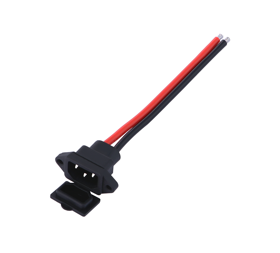
4. Electrical Specifications and Ratings
4.1 Voltage and Current Ratings
The voltage and current ratings of UPS quick-connect connectors must match the requirements of the UPS system and the load it serves. Key rating considerations include:
Input voltage: UPS systems are available for single-phase 120 V, 208 V, 230 V, and 240 V applications, as well as three-phase 208 V, 400 V, and 480 V configurations. The input connector must be rated for the system voltage with an appropriate safety margin.
Output voltage: The output voltage typically matches the input voltage, though some UPS systems provide voltage regulation or conversion. Output connectors must be rated for the maximum output voltage under all operating conditions.
Current rating: The connector must be rated for the maximum continuous current of the UPS, plus a margin for overload conditions. For example, a 10 kVA UPS at 208 V draws approximately 48 A per phase, requiring connectors rated for at least 60 A.
Continuous vs. peak current: Some loads, particularly those with motors or capacitive inputs, draw inrush currents significantly higher than their steady-state current. Connectors must be selected with adequate margin for these transient conditions.
4.2 Three-Phase Configurations
Three-phase UPS systems require connectors that accommodate three phase conductors, a neutral, and a ground. IEC 60309 connectors in the 5-pin configuration (3P+N+PE) are commonly used for this purpose. The clock position and pin arrangement ensure that the connector can only be mated with a compatible outlet, preventing phase mismatches that could damage equipment or create safety hazards.
For higher-current three-phase applications, hardwired terminal blocks are often preferred over plug-and-socket connectors. Above approximately 10 kVA, most UPS units drop plugs entirely and are hardwired to a terminal block by an electrician. This approach provides a more secure, lower-resistance connection and eliminates the risk of accidental disconnection. However, it also reduces serviceability, as disconnecting the UPS requires working with live terminals or de-energizing the circuit.
4.3 Contact Resistance and Thermal Performance
Contact resistance in UPS connectors directly affects voltage drop, power loss, and heat generation. For a 32 A connector with 0.5 milliohms of contact resistance, the resistive heating is approximately 0.5 watts per contact—negligible in isolation but significant when multiplied across multiple poles and connectors in a power distribution chain.
Connector manufacturers specify maximum contact resistance for their products. High-quality quick-connect connectors typically achieve contact resistance in the range of 0.1 to 0.5 milliohms per contact. The use of silver or gold plating on contact surfaces reduces resistance and maintains stable performance over repeated mating cycles.
5. Configuration and Architecture in Data Center UPS Systems
5.1 UPS Topologies and Connector Implications
The choice of UPS topology—standby, line-interactive, or double-conversion—influences connector requirements. Double-conversion UPS systems, which provide the highest level of power conditioning and are standard in data centers, require input and output connections that can handle the full load current continuously. Standby and line-interactive UPS systems may have different input and output current profiles depending on their operating modes.
Modular UPS systems present unique connector requirements. These systems consist of multiple power modules that can be added or removed while the UPS remains online. Quick-connect connectors on the power modules enable hot-swap replacement without de-energizing the entire system. The connectors must be rated for the full module current and must provide reliable contact even after repeated mating cycles.
5.2 Maintenance Bypass Configurations
Maintenance bypass is an essential feature of data center UPS installations. It allows the UPS to be taken offline for service or replacement while the load continues to receive power directly from the utility. Quick-connect connectors play a critical role in bypass configurations.
A typical maintenance bypass arrangement includes a bypass switch or panel that transfers the load from the UPS output to the utility source. The connectors on the bypass panel must be compatible with the UPS input and output connectors, and the transfer mechanism must ensure “make before break” operation to prevent any interruption to the load. Eaton's Hotswap MBP, for example, provides a patented connector that combines input, output, and signal connections with a make-before-break feature, allowing full servicing of the UPS while maintaining electrical continuity to the load.
Vertiv's Liebert MicroPOD is another example of an external maintenance bypass solution. It provides a manual transfer of power from the UPS to the utility source, allowing the UPS to be serviced without powering down connected equipment.
5.3 Connectorized Cable Assemblies
For large data center deployments, connectorized cable assemblies offer a factory-terminated alternative to field-wired connections. Harting, for example, offers a range of connectorized cable assemblies based on its Han-Eco modular connector family that link UPS systems to power distribution units (PDUs). These assemblies are pre-terminated and tested at the factory, reducing installation time and eliminating the risk of field wiring errors. They also enable quick and easy disconnection and reconnection, facilitating maintenance and reconfiguration.
The use of connectorized assemblies is particularly advantageous in prefabricated data center modules, where the entire power distribution system is assembled and tested off-site before delivery. The quick-connect interfaces allow the modules to be rapidly interconnected on-site, reducing construction schedules and improving quality control.
6. Safety, Standards, and Compliance
6.1 IEC 60309 Standard Framework
The IEC 60309 series provides the foundational standard for industrial plugs, socket-outlets, and couplers used in UPS applications. IEC 60309-1 specifies general requirements, while IEC 60309-2 details requirements for products with pin configurations that ensure interchangeability based on voltage and frequency. IEC 60309-4 covers self-contained products that combine a socket-outlet or connector with a switching device, which is directly relevant to maintenance bypass and switched UPS outlet applications.
Compliance with IEC 60309 ensures that connectors from different manufacturers are mechanically and electrically interchangeable, provided they have the same voltage, current, and pin configuration ratings. This interchangeability is essential in data center environments where equipment from multiple vendors must work together seamlessly.
6.2 North American Requirements
In North America, UPS connectors must comply with applicable sections of NFPA 70 (the National Electrical Code) and be listed by a recognized testing laboratory such as UL. The specific requirements depend on the application:
Input connections: Must be rated for the available fault current and protected by an appropriately sized overcurrent device.
Output connections: Must be rated for the continuous output current of the UPS and must provide a means of disconnection that is accessible to qualified personnel.
Battery connections: Must be rated for the battery voltage and current, and must include appropriate overcurrent protection.
UL 486A-486B covers wire connectors and is referenced by NFPA 70 for specific types and combinations of conductors. Busbar and terminal connections in UPS systems must comply with these requirements to ensure safe and reliable operation.
6.3 Hot-Plug Safety
Hot-plugging—connecting or disconnecting a connector while current is flowing—introduces additional safety considerations. The connector must be designed to extinguish any arc that forms during disconnection, and the contact sequence must ensure that ground and neutral connections are made first and broken last.
For high-current UPS applications, hot-plug connectors typically use a “last-mate, first-break” ground contact and a carefully sequenced contact arrangement to minimize arc duration and energy. The connector housing must also be designed to contain any arc products and prevent them from reaching the operator.
7. Emerging Trends and Future Directions
7.1 Higher Power Densities
As rack power densities increase, UPS systems are following suit. A UPS that served a 100 kW rack five years ago may now need to support 300 kW or more. This trend is driving connector manufacturers to develop higher-current quick-connect solutions with improved thermal performance. The transition to 800 V DC distribution, discussed in the context of busbar systems, will also affect UPS connector requirements, as higher voltages reduce current but increase dielectric and arc-suppression challenges.
7.2 Integrated Monitoring and Intelligence
The integration of sensing and communication capabilities into UPS connectors is an emerging trend. Smart connectors can monitor contact temperature, current, and voltage, transmitting this data to the UPS management system for real-time monitoring and predictive maintenance. This capability enables operators to detect degrading connections before they fail, schedule maintenance during planned windows, and optimize the utilization of UPS capacity.
7.3 Standardization and Interoperability
The data center industry is increasingly focused on standardization to reduce costs, simplify deployment, and improve interoperability. Initiatives such as the Open Compute Project (OCP) are driving standardization of power distribution interfaces, including connector specifications. While proprietary quick-connect systems offer performance advantages, the long-term trend is toward greater standardization, which benefits operators by reducing vendor lock-in and simplifying spare parts management.
7.4 Compact and High-Density Connectors
Space is at a premium in modern data centers. Connector manufacturers are responding with increasingly compact designs that deliver high current in smaller footprints. Micro-Fit and Nano-Fit connector families, for example, provide high-density power interconnection for server racks and UPS internal connections, enabling more efficient use of rack space. Molex's EXTreme Guardian power connector system achieves an 11 mm pitch with 80 A per blade, delivering high current density per inch while maintaining the reliability required for UPS and server applications.
8. Specification and Selection Guidelines
8.1 Matching Connectors to UPS Capacity
The first step in specifying UPS quick-connect connectors is to determine the UPS capacity and the associated current requirements. As a rule of thumb:
UPS systems below 3 kVA typically use NEMA 5-15 or 5-20 connectors.
UPS systems from 3 kVA to 10 kVA may use NEMA L5-30 or L6-30 connectors, or IEC 60309 32 A connectors.
UPS systems above 10 kVA are typically hardwired to terminal blocks, though IEC 60309 63 A and 125 A connectors may be used for specific applications.
8.2 Environmental Considerations
The operating environment influences connector selection. In data center white space, where temperature and humidity are controlled, standard connectors are adequate. In mechanical rooms, where temperature and humidity may vary, connectors with higher ingress protection ratings (IP54 or IP67) may be required. In coastal or industrial locations, corrosion-resistant plating and materials should be specified.
8.3 Serviceability and Maintenance
The connector system should be designed to facilitate maintenance and service. Key considerations include:
Accessibility: Connectors should be accessible without removing adjacent equipment or de-energizing circuits unnecessarily.
Labeling: Input, output, and bypass connectors should be clearly labeled to prevent errors during maintenance.
Interchangeability: Where possible, standard connectors should be used to simplify spare parts management and reduce the risk of incompatible replacements.
Hot-swap capability: For critical applications, hot-plug connectors that allow replacement under load should be specified.
UPS quick-connect connectors are critical components that bridge the gap between the UPS system and the power infrastructure it serves. Their design and specification directly affect installation cost, operational reliability, and maintenance efficiency. The principal connector families—IEC 60320, IEC 60309, NEMA, and proprietary quick-connect systems—each have their appropriate applications, and selecting the right connector requires a thorough understanding of the UPS capacity, load characteristics, environmental conditions, and serviceability requirements.
The standards framework, anchored by IEC 60309 and supplemented by national requirements such as NFPA 70 and UL listings, provides a baseline for safety and interchangeability. Compliance with these standards ensures that connectors perform as expected under normal and fault conditions.
Looking forward, the trends toward higher power densities, integrated monitoring, and standardization will continue to shape UPS connector design. As data centers evolve to support AI, edge computing, and other demanding workloads, the humble quick-connect connector will remain a critical—and increasingly sophisticated—element of the power reliability chain. The industry's ability to deliver on the promise of always-on computing depends, in no small part, on the quality and reliability of these essential components.
 Yang.taya@aitmpower.com
Tel: 15382891313
Phone: 0769-88878951
Fax: 0769-88878955
Wechat: 15382891313


 CN
 CN
 Home >