
 2026-10-14
 3
The 120A Energy Storage Quick-Connect Connector represents a critical component in modern battery energy storage systems (BESS), electric vehicles, and industrial power distribution architectures. This comprehensive analysis examines the technical specifications, design principles, material science considerations, safety mechanisms, application scenarios, and market positioning of 120A-rated quick-connect connectors. Drawing upon manufacturer data and industry standards, this document provides engineers, system integrators, and procurement specialists with a detailed understanding of how these connectors function within the broader energy storage ecosystem. The analysis reveals that 120A quick-connect connectors serve as a pivotal interface between compact design requirements and high-power transmission needs, bridging the gap between lower-current battery interconnects and heavy-duty 150A+ panel-mount solutions.
Energy storage systems have emerged as indispensable infrastructure in the global transition toward renewable energy and electrified transportation. From utility-scale battery installations that stabilize electrical grids to compact residential storage units that manage solar-generated power, the reliability and efficiency of these systems depend fundamentally on the integrity of their electrical interconnections. Connectors serve as the critical nexus where power flows from batteries to inverters, from modules to racks, and from storage banks to the broader electrical infrastructure.
The connector market for energy storage applications has experienced substantial growth, driven by several converging trends. The proliferation of electric vehicles has created demand for high-current, high-voltage connectors capable of handling the substantial power requirements of modern battery packs. Simultaneously, the expansion of grid-scale energy storage installations has necessitated connectors that can operate reliably under continuous high-load conditions while withstanding environmental challenges ranging from temperature extremes to moisture ingress. Furthermore, the modularization of battery systems—wherein individual battery modules can be swapped or serviced independently—has placed a premium on connectors that facilitate quick, tool-free disconnection and reconnection without compromising electrical integrity or safety.
Within the spectrum of energy storage connectors, the 120A quick-connect connector occupies a distinctive position. This current rating places it squarely in the medium-to-high power range, suitable for applications that demand substantial current-carrying capacity without requiring the heaviest infrastructure associated with 200A+ connectors. The "quick-connect" designation refers to the connector's design philosophy: it is engineered for rapid, often tool-free mating and unmating, enabling efficient assembly during manufacturing and straightforward serviceability in field conditions.
The 120A rating is meaningful in the context of battery architecture. Many energy storage systems are configured with battery modules that operate at voltages ranging from 48V to over 1000V DC. At 120A, a connector can transmit substantial power—12kW at 100V, 60kW at 500V, or 120kW at 1000V—making it suitable for a wide array of applications from commercial energy storage cabinets to electric vehicle battery packs. This current level also aligns with common wire sizes in the 25mm² to 35mm² range (approximately 3–2 AWG), allowing system designers to balance conductor cost against power transmission requirements.
This document aims to provide a thorough technical examination of 120A energy storage quick-connect connectors, addressing multiple dimensions of their design, performance, and application. The analysis begins with a foundational discussion of connector fundamentals, establishing the electrical and mechanical principles that govern their operation. Subsequent sections delve into specific technical specifications, material selection criteria, safety mechanisms, environmental considerations, and application scenarios. The document also examines industry standards and certifications, comparative analysis with related connector categories, and future trends that may influence connector evolution. Throughout, the discussion is grounded in concrete manufacturer specifications and empirical data from commercially available products, ensuring that the analysis remains practical and actionable for engineering professionals.
The electrical performance of a 120A energy storage quick-connect connector is defined by several interrelated parameters that collectively determine its suitability for specific applications.
Rated Current and Voltage: The foundational specification for any power connector is its current-carrying capacity. For 120A connectors, the rated current represents the maximum continuous current the connector can handle under specified conditions, typically with a temperature rise not exceeding a defined threshold (commonly 30–45K above ambient). This rating is contingent upon proper installation, including correct wire gauge selection and appropriate torque application for crimped or screw-terminated connections.
The rated voltage for these connectors varies by product but commonly falls in the 1000V to 1500V DC range. This high voltage capability reflects the demands of modern battery systems, which increasingly operate at higher voltages to reduce current for a given power level, thereby minimizing resistive losses and conductor cross-sections. A connector rated for 1000V DC can safely operate in systems where the maximum potential difference between any two conductors does not exceed this value.
Contact Resistance: The resistance of the electrical interface directly influences both power loss and heat generation. High-quality 120A connectors typically exhibit contact resistance values in the range of 0.5 mΩ or less. At 120A, a contact resistance of 0.5 mΩ results in a power dissipation of approximately 7.2W at the contact interface—a manageable level that contributes to stable thermal performance. Some manufacturers achieve even lower resistance through advanced contact designs, such as the RADSOK® technology employed by Amphenol, which uses a hyperbolic grid configuration to maximize contact surface area while maintaining a compact form factor.
Insulation Resistance: The dielectric properties of the connector's insulating materials determine its ability to prevent unintended current flow between isolated conductors. Insulation resistance specifications for energy storage connectors are typically stated as exceeding 2000 MΩ or even 5000 MΩ at specified test voltages. This high resistance ensures minimal leakage current, which is particularly important in high-voltage systems where even small leakage currents can pose safety hazards or degrade system efficiency.
Dielectric Withstand Voltage: This parameter, often called the hipot (high potential) test voltage, defines the maximum voltage the connector's insulation can withstand without breakdown. For 120A energy storage connectors, dielectric withstand voltage ratings commonly range from 3000V AC to 5000V DC. This substantial margin above the rated operating voltage provides protection against transient overvoltages that may occur during switching operations, fault conditions, or lightning-induced surges.
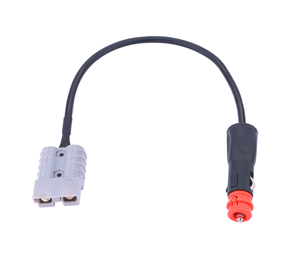
Mating and Unmating Forces: The ergonomics of connector engagement and disengagement are governed by insertion and withdrawal force specifications. For 120A connectors, insertion forces typically fall in the range of 50–100N, while withdrawal forces may be similar or somewhat higher depending on the locking mechanism. These values represent a balance between ensuring secure, low-resistance contact and enabling manual operation without excessive effort. Connectors designed for frequent mating cycles often incorporate features such as cam-action levers or push-pull mechanisms to reduce the perceived effort required for connection.
Mechanical Life: The durability of a connector over repeated mating cycles is expressed as its mechanical life rating. Typical 120A energy storage connectors are rated for 100 to 200 mating cycles. This rating assumes proper handling and alignment during mating; abusive practices such as forced engagement or misalignment can significantly reduce connector lifespan. The mechanical life specification is particularly relevant for applications where battery modules are regularly swapped or serviced, such as in certain fleet vehicle or modular energy storage scenarios.
Wire Size Compatibility: The conductor size that a connector can accommodate determines its practical current-carrying capacity and installation requirements. 120A energy storage quick-connect connectors commonly support wire cross-sections of 25mm² (approximately 3 AWG) or up to 35mm² depending on the specific product. Some connectors offer flexibility in wire range, accommodating multiple conductor sizes within their clamping or crimping mechanisms. The relationship between wire size and current capacity follows standard ampacity tables, which account for conductor material, insulation type, and installation conditions.
Termination Method: The method by which the conductor is attached to the connector contact significantly influences both electrical performance and long-term reliability. Common termination methods for 120A connectors include:
Crimping: The conductor is compressed into the contact barrel using a calibrated crimping tool, creating a cold weld between conductor and contact. Crimping offers excellent electrical and mechanical performance when performed with proper tooling and technique.
Screw Termination: The conductor or a busbar is secured using a threaded fastener. This method facilitates field installation and rework but requires proper torque application to ensure stable contact resistance over time.
Busbar Connection: Some connectors are designed for direct busbar attachment, eliminating the need for cable termination and reducing overall system complexity.
Ingress Protection (IP Rating): The IP rating, defined by IEC 60529, quantifies a connector's resistance to dust and water ingress. Most 120A energy storage connectors carry an IP67 rating, indicating complete protection against dust and the ability to withstand temporary immersion in water up to 1 meter depth. Some manufacturers offer IP68-rated products for applications requiring continuous submersion or exposure to high-pressure water spray. The IP rating is particularly critical for connectors used in outdoor energy storage installations, electric vehicles, and industrial environments where moisture, dust, and contaminants are present.
Operating Temperature Range: The ambient temperature range over which a connector can operate reliably is typically specified as -40°C to +125°C for energy storage connectors. This wide range accommodates applications from cold-climate installations to high-temperature industrial environments. It is important to distinguish between ambient temperature rating and the temperature rise that occurs during current-carrying operation; the connector's maximum operating temperature must account for both the ambient conditions and the self-heating from resistive losses.
Flammability Rating: The plastic materials used in connector housings and insulators must meet flammability standards to minimize fire risk in the event of an electrical fault. UL 94-V0 is the most common flammability rating for energy storage connectors, indicating that the material self-extinguishes within 10 seconds when removed from an ignition source, with no dripping of flaming material. This rating is particularly important for connectors used in enclosed battery compartments or other confined spaces where fire propagation could have catastrophic consequences.
Salt Spray Resistance: For connectors deployed in coastal or marine environments, salt spray resistance is a critical durability parameter. Some 120A connectors are tested to withstand 72 hours of salt spray exposure without significant corrosion or performance degradation. This specification reflects the use of corrosion-resistant materials and coatings in the contact system and housing.
| Parameter | Typical 120A Quick-Connect | Range Across Products |
|---|---|---|
| Rated Current | 120A | 120A |
| Rated Voltage | 1000–1500V DC | 600–1500V DC |
| Contact Resistance | ≤0.5 mΩ | 0.5–1 mΩ |
| Insulation Resistance | ≥2000 MΩ | 2000–5000 MΩ |
| Dielectric Withstand | 3000V AC | 3000–5000V |
| Mating Cycles | 100–200 | 100–10000 |
| Wire Size | 25–35mm² | 16–35mm² |
| IP Rating | IP67 | IP67–IP68 |
| Operating Temp | -40°C to +125°C | -40°C to +125°C |
| Flammability | UL 94-V0 | UL 94-V0 |
The heart of any high-current connector is its contact system—the interface where electrical current transfers from one conductor to another. For 120A energy storage connectors, contact design must address several competing requirements: maximizing contact area to minimize resistance, maintaining stable contact pressure over many mating cycles, dissipating heat efficiently, and ensuring reliable engagement even under conditions of vibration or thermal cycling.
Contact Geometry: Several contact geometries are employed in 120A connectors. Traditional pin-and-socket designs use a cylindrical pin that engages with a corresponding socket, with contact pressure provided by spring elements in the socket. This design is simple and robust but may have limited contact area for a given envelope size.
More advanced designs, such as the RADSOK® technology used in Amphenol's SurLok Plus series, employ a hyperbolic grid structure that creates multiple contact points around the circumference of the pin. This configuration increases the effective contact area without increasing the connector's physical dimensions, resulting in lower contact resistance and better heat dissipation. The RADSOK design also provides a wiping action during mating that helps clean contact surfaces of oxides and contaminants.
Contact Material and Plating: The base material for high-current contacts is typically a copper alloy, selected for its excellent electrical conductivity and mechanical strength. Copper alloys such as tellurium copper or beryllium copper offer a balance of conductivity, hardness, and spring properties that make them suitable for contact applications.
Contact surfaces are invariably plated to prevent oxidation, reduce contact resistance, and extend service life. Silver plating is the most common choice for energy storage connectors, offering the lowest electrical resistance of any practical contact material and excellent resistance to oxidation. Gold plating is sometimes used for signal contacts or in applications requiring extremely stable low-level contact resistance, but its higher cost makes it less common for power contacts. Nickel underplating is often applied beneath silver or gold to act as a diffusion barrier and improve adhesion.
Contact Pressure and Spring Design: Maintaining adequate contact pressure is essential for stable low-resistance connections. The spring elements that provide this pressure must be designed to maintain their force over the connector's rated life, resisting stress relaxation at elevated temperatures. Stainless steel springs are commonly used for this purpose, offering high strength and corrosion resistance. In some designs, the spring is integral to the socket contact, while in others, separate spring components are employed.
The connector housing serves multiple functions: it mechanically supports and aligns the contacts, provides electrical insulation between circuits, protects internal components from environmental ingress, and contributes to the overall safety of the connector by preventing accidental contact with live parts.
Material Selection: The insulating materials used in energy storage connector housings must meet demanding requirements. They must possess high dielectric strength to withstand the connector's rated voltage plus safety margin, high tracking resistance to prevent surface conduction under contaminated conditions, good mechanical strength and impact resistance, and appropriate thermal properties to maintain dimensional stability across the operating temperature range.
Common housing materials for 120A connectors include glass-filled nylons and other engineering thermoplastics. These materials offer an excellent balance of electrical, mechanical, and thermal properties, along with the ability to be molded into complex shapes with tight tolerances. The UL 94-V0 flammability rating is a baseline requirement for these applications.
Sealing Systems: Environmental sealing is achieved through the use of elastomeric gaskets, O-rings, and overmolded seals. Silicone rubber is a common sealing material due to its wide temperature range, excellent compression set resistance, and good dielectric properties. The sealing system must maintain its integrity through repeated mating cycles and across the full operating temperature range.
Keying and Polarization: To prevent mismating—connecting a plug to an incompatible receptacle—connectors incorporate keying features that allow mating only in the correct orientation and only between compatible halves. This prevents scenarios such as connecting a battery pack to a charger of incorrect voltage or connecting modules that should remain isolated. Keying features may include asymmetric pin arrangements, molded tabs or slots, or color-coding schemes.
A reliable locking mechanism ensures that once mated, the connector halves remain securely engaged despite vibration, thermal cycling, or accidental forces. For 120A connectors, locking mechanisms must provide sufficient retention force while still permitting intentional disconnection.
Push-In Lock: Many quick-connect connectors employ a push-in locking mechanism, where the act of mating automatically engages a latch that secures the connection. Disconnection requires either pressing a release button or lever, or applying a deliberate pull force that overcomes the latch. This design facilitates rapid, one-handed connection while preventing accidental separation.
Spring Lock: Spring-based locking mechanisms use the elastic force of a spring to maintain engagement. The connector may feature a spring-loaded collar or clip that snaps into a groove or over a ridge on the mating half. Spring locks offer reliable retention and are generally easy to operate.
Threaded Locking: Some connectors employ threaded couplings, where a rotating collar or nut secures the connection. Threaded locking provides the highest retention force and is often used in applications subject to severe vibration or where accidental disconnection could have serious consequences. However, threaded locking requires more time and effort for connection and disconnection compared to quick-connect designs.
Secondary Locking Features: Some connectors incorporate secondary locking mechanisms that provide redundancy beyond the primary latch. These may include locking rings, safety clips, or tamper-resistant features. Secondary locks are particularly valuable in safety-critical applications where unintended disconnection could expose live conductors or interrupt critical power.
The performance of a 120A connector is fundamentally determined by the properties of its conductive materials. Copper and its alloys form the basis of virtually all high-current contact systems due to copper's exceptional electrical conductivity—second only to silver among common metals.
Copper Alloys: Pure copper, while highly conductive, lacks the mechanical strength and spring properties required for many contact applications. Copper alloys address this limitation by incorporating elements such as beryllium, tellurium, chromium, or zirconium. Beryllium copper (BeCu) offers an excellent combination of conductivity, strength, and spring properties, making it a preferred material for spring contacts and high-reliability applications. Tellurium copper provides good machinability and conductivity, while chromium copper offers high strength and resistance to softening at elevated temperatures.
Silver Plating: The silver plating on contact surfaces serves several critical functions. Silver has the highest electrical conductivity of any metal, and its oxide is conductive (unlike copper oxide), ensuring that contact resistance remains low even after exposure to air. Silver plating also provides a soft, ductile surface that conforms to mating surfaces under contact pressure, increasing the effective contact area. The thickness of silver plating on power contacts typically ranges from 3 to 10 micrometers, with thicker platings offering greater durability but higher cost.
Contact Resistance Considerations: The contact resistance between two mated surfaces is influenced by several factors beyond the intrinsic resistivity of the materials. Surface roughness determines the actual contact area—only the asperities (microscopic high points) of the surfaces actually touch. Contact pressure deforms these asperities, increasing the real contact area and reducing resistance. The presence of oxide films or contamination layers can dramatically increase resistance, which is why contact surfaces are typically cleaned and plated. The wiping action during mating helps displace contaminants and break through oxide layers.
The selection of insulating materials for connector housings and internal components involves balancing multiple, sometimes competing, requirements.
Thermoplastics: Engineering thermoplastics are the predominant materials for connector housings. Glass-filled nylons (such as PA66 with 30% glass fiber) offer high mechanical strength, good dielectric properties, and excellent resistance to many chemicals and solvents. Polybutylene terephthalate (PBT) and polyethylene terephthalate (PET) are also used, offering good dimensional stability and electrical properties. The choice of base polymer and filler content affects properties such as strength, stiffness, thermal expansion, and flammability.
Silicone Elastomers: For sealing applications, silicone rubber is widely used due to its wide temperature range (-50°C to +200°C), excellent compression set resistance, and good dielectric properties. Silicone gaskets and O-rings can maintain their sealing force over many years and through numerous thermal cycles, making them ideal for connectors expected to provide long-term environmental protection.
Flame Retardants: To achieve UL 94-V0 flammability ratings, flame retardant additives are incorporated into housing materials. These additives may include halogenated compounds, phosphorus-based systems, or mineral fillers such as aluminum trihydrate. The choice of flame retardant system must be compatible with the base polymer and must not adversely affect mechanical or electrical properties. Environmental considerations are also increasingly important, with some halogenated flame retardants facing regulatory restrictions.
Injection Molding: Connector housings and many internal insulating components are produced by injection molding, a process that allows high-volume production of complex, precision parts. The molding process must be carefully controlled to ensure proper filling, minimize internal stresses, and maintain dimensional tolerances. Multi-shot molding processes can produce parts with integrated seals or multiple materials in a single operation.
Contact Stamping and Forming: High-current contacts are often produced by stamping and forming from metal strip. Progressive die stamping can produce complex contact geometries at high speed, with subsequent forming operations creating the three-dimensional shapes required for spring elements and mating interfaces. For larger contacts, machining operations may be employed.
Plating Processes: Electroplating is the standard method for applying silver, gold, or nickel coatings to contact surfaces. The plating process must be carefully controlled to achieve uniform thickness, good adhesion, and the desired surface properties. Barrel plating is commonly used for small contacts, while rack plating may be employed for larger components.
Assembly and Quality Control: Connector assembly involves integrating contacts, springs, seals, and housings into a finished product. Automated assembly equipment is often used to achieve consistent quality and high production rates. Quality control measures may include dimensional inspection, electrical testing (contact resistance, dielectric withstand), and functional testing (mating force, locking mechanism operation).
Touch protection, also known as finger-proofing, is a critical safety feature for energy storage connectors. It prevents accidental contact with live conductors during mating, unmating, or in the event of partial disconnection. For 120A connectors operating at high voltages, touch protection is essential for preventing electric shock.
Design Approaches: Touch protection is achieved through the geometry of the connector housing and contacts. In a typical design, the receptacle (the fixed half of the connector) has recessed contacts that are not accessible to fingers or tools. The plug (the removable half) has contacts that are shrouded by the housing, so they cannot be touched even when the connector is unmated. Mating brings the contacts together within the enclosed space of the connector housing, where they remain inaccessible until the connector is fully unmated.
Standards and Testing: Touch protection is evaluated according to standards such as IEC 60529 (for IP ratings) and UL 2251 (for EV connectors). The standard test involves attempting to insert a jointed test finger (simulating a human finger) into any opening in the connector to verify that it cannot contact live parts. Connectors meeting the touch-proof requirement are typically marked or described as such.
Hot plugging—connecting or disconnecting a connector while current is flowing—presents a significant safety challenge. The electrical arc that forms when contacts separate under load can erode contact surfaces, generate intense heat, and potentially ignite surrounding materials or cause injury to personnel.
Hot Plug Ratings: Some 120A connectors are rated for hot plugging at specified current levels. Anderson Power's SB® Smart connectors, for example, are rated for hot plug capable up to 60A at 120VDC for power contacts and 5A at 120VDC for auxiliary contacts. These ratings reflect the connector's ability to safely interrupt current without damage or hazardous arcing.
Arc Suppression Techniques: Connectors designed for hot plug capability employ several techniques to manage arcing. Magnetic blowout uses a magnetic field to stretch and cool the arc, facilitating its extinction. Arc-resistant materials in the contact area can withstand the thermal energy of the arc without degrading. Sequential mating—where ground and signal contacts engage before power contacts—ensures that the system is properly grounded and monitored before power flows.
Sequencing for Safety: Advanced connectors incorporate sequenced contacts that engage in a specific order during mating. The first-mate, last-break (FMLB) principle is commonly applied: ground contacts engage first during mating and break last during unmating, ensuring that the system is always grounded when power contacts are engaged. High-voltage interlock (HVIL) circuits may also be sequenced to ensure that power is disabled before power contacts separate.
HVIL is a safety mechanism used in high-voltage systems to ensure that power is disconnected before a connector is unmated. An HVIL circuit is a low-voltage signal loop that passes through the connector. When the connector is fully mated, the HVIL circuit is closed, signaling to the system controller that it is safe to apply power. When the connector is unmated or partially unmated, the HVIL circuit opens, causing the controller to immediately disconnect power from the high-voltage conductors.
Implementation: HVIL circuits are typically implemented using dedicated signal contacts within the connector, separate from the power contacts. The signal contacts are arranged to break before the power contacts when the connector is unmated, ensuring that power is removed before the high-voltage interface separates. Some connectors integrate HVIL contacts into the main connector body, while others use a separate, smaller connector for the interlock circuit.
Proper grounding is essential for electrical safety in high-voltage systems. The connector's ground path must have sufficient current-carrying capacity to handle fault currents and must maintain its integrity throughout the connector's life.
Ground Contact Design: In connectors with integrated grounding, a dedicated ground contact is provided, often larger or more robust than signal contacts to handle fault currents. The ground contact is sequenced to engage first and break last, ensuring that the system is always grounded when other contacts are engaged. The ground path resistance is typically specified to be very low, ensuring effective fault current return.
Bonding to Enclosure: In many installations, the connector is mounted to a conductive enclosure or panel, and the ground path includes the mounting interface. Proper bonding requires that the mounting surfaces be clean and free of non-conductive coatings, and that the mounting hardware provides sufficient force to maintain a low-resistance connection over time. Some connectors include dedicated bonding points or hardware to ensure reliable grounding.
While not a feature of the connector itself, thermal management is a critical consideration in the application of 120A connectors. Excessive temperature rise can degrade insulation, accelerate contact oxidation, and ultimately lead to connector failure.
Temperature Rise Limits: Connector specifications typically include a maximum temperature rise at rated current, commonly 30K to 45K above ambient. This limit ensures that the connector's materials remain within their safe operating temperature range and that contact resistance does not increase due to oxidation or stress relaxation.
Thermal Sensors: Some advanced connector systems incorporate temperature sensors that monitor the connector's thermal state in real time. These sensors can trigger derating or shutdown if temperatures exceed safe limits, providing an additional layer of protection against overload or cooling system failure.
Battery energy storage systems represent one of the most significant applications for 120A quick-connect connectors. These systems, which range from residential-scale units of a few kilowatt-hours to utility-scale installations of hundreds of megawatt-hours, rely on connectors to link individual battery modules into strings, strings into racks, and racks into the overall system.
Modular Architecture: Modern BESS are typically designed with a modular architecture, where battery modules can be added, removed, or replaced independently. This modularity requires connectors that facilitate quick, safe disconnection and reconnection without specialized tools. 120A connectors are well-suited to this role, offering sufficient current capacity for module-to-module connections while remaining compact and easy to handle.
Rack-Level Connections: At the rack level, where multiple modules are combined, current levels may exceed the capacity of a single 120A connector. In such cases, multiple 120A connectors may be used in parallel, or the design may transition to higher-current connectors at the rack interface. The choice depends on the specific system architecture and the trade-offs between connector count, cable management complexity, and overall system cost.
BMS Integration: Battery management systems (BMS) require connections for voltage sensing, temperature monitoring, and communication in addition to power connections. Some connector designs integrate signal contacts alongside power contacts, allowing a single connector to serve both power and BMS functions. This integration simplifies wiring and reduces the number of separate connectors required.
The electric vehicle market has been a major driver of innovation in high-current connector technology. While the main traction battery connections in EVs often employ specialized high-voltage connectors with current ratings exceeding 200A, 120A connectors find application in several EV subsystems.
Battery Pack Interconnections: Within the battery pack, individual modules or cell groups may be interconnected using 120A connectors. These connectors must withstand the vibration, temperature cycling, and environmental exposure typical of automotive applications. Quick-connect designs facilitate pack assembly and service, allowing modules to be replaced without extensive rewiring.
Auxiliary Power Systems: EVs and HEVs include auxiliary power systems for functions such as cabin climate control, power steering, and lighting. These systems may operate at lower voltages (12V, 24V, or 48V) and currents within the 120A range. Connectors for these applications must meet automotive reliability standards while providing the ease of assembly and serviceability that quick-connect designs offer.
Charging Infrastructure: While the main charging interface for EVs uses specialized connectors (such as CCS, CHAdeMO, or Tesla's proprietary designs), 120A connectors may be used in charging station internal wiring, connecting power conversion modules to output cables or managing power distribution within the charging cabinet.
Beyond energy storage and transportation, 120A quick-connect connectors serve a variety of industrial and commercial applications where reliable high-current connections are required.
Uninterruptible Power Supplies (UPS): UPS systems rely on battery strings to provide backup power during outages. 120A connectors are used to connect battery strings to the UPS's DC bus, facilitating battery replacement and maintenance. The quick-connect design allows service personnel to isolate and replace battery modules safely and efficiently.
Telecommunications Infrastructure: Telecom base stations and data centers often employ battery backup systems to ensure continuous operation during grid outages. 120A connectors are used in these systems to link battery modules and connect the battery plant to the power distribution equipment. The connectors must meet the reliability and safety standards of the telecommunications industry, including resistance to temperature extremes and environmental contaminants.
Material Handling Equipment: Electric forklifts, automated guided vehicles (AGVs), and other material handling equipment rely on high-current connectors for battery connection. Anderson Power's connectors, including the SB® series, have become industry standards in this application, where rapid battery swapping is often required to minimize equipment downtime. 120A connectors are suitable for medium-sized material handling equipment, providing a balance of current capacity and physical size.
Renewable Energy Systems: Solar photovoltaic (PV) and wind power systems increasingly incorporate battery storage to smooth output and provide dispatchable power. 120A connectors are used in these systems to connect battery banks to inverters and power conversion equipment. The connectors must withstand outdoor environmental conditions, including UV exposure, temperature extremes, and moisture.
| Application | Key Requirements | Typical Connector Features |
|---|---|---|
| Residential BESS | Compact size, easy installation, safety | Touch-proof, IP67, tool-free mating |
| Utility BESS | High reliability, remote monitoring | Temperature sensors, HVIL, robust locking |
| EV Battery Pack | Vibration resistance, thermal cycling | High mating cycle life, sealed, keyed |
| UPS/Telecom | Continuous operation, serviceability | Low resistance, stable contact force |
| Material Handling | Rapid swapping, durability | High cycle life, ergonomic locking |
| Renewable Energy | Environmental resistance | UV stable, IP68, wide temperature range |
The design, testing, and application of 120A energy storage connectors are governed by a framework of international standards that ensure safety, interoperability, and performance consistency.
IEC 61984: This standard, titled "Connectors—Safety requirements and tests," specifies general safety requirements for connectors used in electrical and electronic equipment. It covers aspects such as construction, protection against electric shock, dielectric withstand, temperature rise, and mechanical strength. Connectors meeting IEC 61984 requirements are suitable for a wide range of industrial applications.
UL 4128: Underwriters Laboratories standard UL 4128, "Battery Energy Storage System Connectors," specifically addresses connectors used in battery energy storage applications. It includes requirements for electrical performance, mechanical durability, environmental resistance, and safety features. UL 4128 certification is increasingly required for connectors used in grid-connected energy storage systems in North America.
UL 94: The UL 94 standard for flammability of plastic materials is widely referenced in connector specifications. The V-0 rating, the most stringent of the standard ratings, indicates that the material self-extinguishes within 10 seconds when the flame is removed, with no dripping of flaming material.
IEC 60529: This standard defines the IP (Ingress Protection) rating system for enclosures. Connectors rated IP67, the most common rating for energy storage connectors, are protected against dust ingress and temporary immersion in water.
TUV Certification: TUV Rheinland and similar organizations provide third-party certification of connector compliance with applicable standards. TUV certification is often required for connectors used in European energy storage and electric vehicle applications.
North America: In the United States and Canada, connectors for energy storage applications must typically meet UL standards, including UL 4128 for BESS connectors and UL 1973 for batteries. NEC (National Electrical Code) requirements govern installation practices, including conductor sizing, overcurrent protection, and disconnection means.
Europe: European requirements include compliance with IEC standards and, for certain applications, the CE marking directive. The Low Voltage Directive (LVD) and Electromagnetic Compatibility (EMC) Directive may apply depending on the connector's role in the system. TUV certification is commonly accepted as evidence of compliance with European safety requirements.
China: In the Chinese market, connectors may be required to meet GB (Guo Biao) standards, which are often aligned with IEC standards but may include additional requirements specific to the Chinese market. Certification from the China Quality Certification Centre (CQC) may be required for certain applications.
Electrical Testing: Connectors undergo a battery of electrical tests to verify their performance and safety. These include contact resistance measurement (using four-wire Kelvin methods), dielectric withstand testing (applying high voltage between conductors and between conductors and ground), insulation resistance measurement, and temperature rise testing at rated current.
Mechanical Testing: Mechanical tests evaluate the connector's durability and reliability under mechanical stress. These include mating and unmating force measurement, mechanical life testing (repeated mating cycles), vibration testing, shock testing, and contact retention force measurement.
Environmental Testing: Environmental tests verify the connector's performance under the conditions it will encounter in service. These include thermal cycling (exposure to alternating high and low temperatures), humidity testing, salt spray exposure, and IP rating verification (dust and water ingress tests).
Certification Process: The certification process typically involves submitting product samples to an accredited testing laboratory, where they undergo the applicable tests. If the product meets all requirements, the laboratory issues a test report and, if applicable, a certification mark (such as the UL mark or TUV mark) can be applied to the product. Ongoing compliance may require periodic follow-up inspections at the manufacturing facility.
Energy storage connectors are available in a wide range of current ratings, from small signal connectors carrying less than 1A to heavy-duty busbar connectors rated for several thousand amperes. Understanding where the 120A category fits within this spectrum helps illuminate its appropriate applications and limitations.
Low-Current Connectors (Below 50A): Connectors in the 10–50A range are used for auxiliary circuits, signal transmission, and small battery systems. They are typically compact, cost-effective, and may not require the robust sealing and locking features of higher-current connectors.
Medium-Current Connectors (50–150A): The 120A connector falls within this range, which represents the "sweet spot" for many battery module interconnections and medium-power distribution applications. Connectors in this range balance current capacity against physical size, cost, and ease of use.
High-Current Connectors (150–400A): Above 150A, connectors become progressively larger and more robust. The 150A category, discussed in the following section, represents a step up in current capacity with corresponding increases in contact size, wire gauge, and often mounting complexity.
Very High-Current Connectors (Above 400A): For currents exceeding 400A, connectors typically employ busbar connections rather than cables, and may use forced cooling or parallel contact systems to manage heat. These connectors are used in main power distribution, large battery strings, and heavy industrial applications.
Contact Size and Mass: Higher current ratings require larger contacts to reduce current density and manage heat generation. A 120A connector's contacts are substantially smaller and lighter than those of a 150A or 200A connector, which can be an advantage in space-constrained or weight-sensitive applications.
Wire Gauge and Bend Radius: The conductor size required for a given current increases with the current rating. A 120A connector typically accommodates 25–35mm² wire, while a 150A connector may require 35–50mm², and higher-current connectors use even larger conductors. Larger conductors are stiffer and have larger minimum bend radii, which can complicate routing in tight spaces.
Mating Force: Contact mating force generally increases with contact size, as larger contacts require more spring force to achieve adequate contact pressure. A 120A connector may require 50–100N of insertion force, while a 150A connector might require 75–150N. The increased force can be managed through lever-assisted or cam-action mechanisms, but these add complexity and cost.
Cost: Connector cost increases with current rating, reflecting the larger quantity of materials (copper, silver, plastic), more complex manufacturing processes, and additional testing requirements. For a given application, the cost-optimal current rating is the lowest rating that meets the current-carrying requirements with an appropriate margin.
When selecting a connector current rating for a specific application, system designers must consider several factors beyond the nominal current requirement.
Continuous vs. Peak Current: The rated current of a connector typically applies to continuous operation. If the application involves high peak currents of short duration, a lower-rated connector may suffice, provided the thermal time constant prevents excessive temperature rise during peaks. Conversely, if the current is continuous at or near the rated value, additional margin may be advisable.
Ambient Temperature: Connector current ratings are typically specified at a reference ambient temperature (often 25°C or 30°C). At higher ambient temperatures, the connector's current-carrying capacity must be derated to avoid exceeding temperature limits. A 120A connector operating at 50°C ambient may only be suitable for 90–100A.
Altitude and Airflow: At high altitudes, reduced air density impairs convective cooling, potentially requiring current derating. Similarly, connectors in enclosed spaces with poor airflow may run hotter than those in well-ventilated locations.
Future Expansion: System designers may choose a higher-rated connector than the initial application requires to accommodate future upgrades or expansions. This "design margin" approach can avoid the need for costly rework if current requirements increase.
The market for 120A energy storage connectors includes several established manufacturers, each offering products with distinctive features and capabilities.
Amphenol Industrial: Amphenol's SurLok Plus series includes 120A and 150A connectors featuring RADSOK® contact technology. These connectors are widely used in electric vehicles, energy storage, and industrial applications. The company also offers the EnergyKlip and BarKlip series for energy storage applications.
Degson Electronics: Degson manufactures a range of energy storage connectors, including the ESS series. Their products are characterized by robust construction, UL 4128 compliance, and competitive pricing.
Anderson Power Products: Anderson Power's SB® and SB Smart® series are industry standards in material handling, telecommunications, and other applications requiring reliable high-current connections. The SB Smart series integrates power and signal contacts in a single connector, enabling intelligent battery management.
TE Connectivity: TE's HPC (High Power Connector) series includes connectors rated for 350A and higher, with some models applicable to lower-current applications. TE connectors feature integrated temperature sensors and smart locking systems.
QC Solar: QC Solar's QCES series energy storage connectors offer 120A capability with features such as 360° rotation, tool-free installation, and IP68 protection.
| Feature | Amphenol SurLok Plus | Degson ESS | Anderson SB Smart | QC Solar QCES |
|---|---|---|---|---|
| Current Rating | 120A/150A | 50A–150A | 230A (power) | 120A |
| Voltage Rating | 1000V DC | 1000–1500V DC | 600V | 1500V DC |
| Contact Technology | RADSOK | Pin/Socket | Flat-wipe | Pin/Socket |
| IP Rating | IP67 | IP67 | IP64/IP68 | IP68 |
| Mating Cycles | 100+ | 100 | 10,000 | 100 |
| Signal Integration | Optional | No | Yes (16 poles) | Optional |
| Locking | Spring | Push-in | Spring | Dual button |
| Keying | Yes | Yes | Selective | Yes |
120A energy storage connectors are available through a variety of distribution channels, including:
Authorized Distributors: Companies such as RS Components, Mouser, Digi-Key, and TME stock connectors from major manufacturers, offering technical support and often same-day shipping.
Direct from Manufacturer: For large-volume orders or custom configurations, purchasing directly from the manufacturer may offer cost advantages and access to engineering support.
Online Marketplaces: Consumer-oriented platforms such as Amazon list generic and branded connectors, though product quality and documentation may be inconsistent.
Pricing for 120A connectors varies widely based on brand, features, and quantity. Generic connectors may cost €20–30 each, while branded products with advanced features may cost €50–100 or more. For accurate pricing, contacting distributors or manufacturers directly is recommended.
The trend toward higher system voltages in energy storage and electric vehicles is placing new demands on connector technology. While 1000V DC systems are currently common, 1500V DC systems are increasingly being adopted for utility-scale energy storage, and some automotive systems are moving toward 800V or even higher voltages.
Higher voltages require connectors with increased dielectric withstand capability, greater creepage and clearance distances, and more robust insulation systems. Connectors rated for 1500V DC are already available from several manufacturers, and the industry is likely to see continued development of connectors for even higher voltages.
The integration of sensors and communication capabilities into connectors is an emerging trend that promises to enhance safety and enable predictive maintenance. Temperature sensors embedded in connectors can monitor thermal conditions in real time, allowing system controllers to derate or shut down before damage occurs. Current sensors can provide accurate power measurement for battery state-of-charge estimation. Identification features—such as EEPROM chips that store connector specifications and usage history—can ensure that only compatible components are mated and can track connector life for maintenance scheduling.
The demand for higher power in smaller packages continues to drive innovation in contact design and thermal management. Advanced contact technologies, such as the RADSOK® hyperbolic grid, enable higher current density than traditional pin-and-socket designs. Improved thermal materials and designs help dissipate heat more effectively, allowing connectors to operate at higher currents within the same envelope.
Environmental regulations and corporate sustainability goals are influencing connector design and material selection. Restrictions on hazardous substances (such as the EU's RoHS directive) limit the use of certain flame retardants and other additives. The trend toward halogen-free materials eliminates the risk of toxic halogenated compounds being released in a fire. Design for recyclability encourages the use of separable materials and reduces the use of composite structures that are difficult to disassemble.
As the energy storage industry matures, there is growing pressure for connector standardization to ensure interoperability between components from different manufacturers. While proprietary connector designs offer performance advantages, they can lock customers into a single supplier and complicate system integration. Industry consortia and standards bodies are working to develop specifications for energy storage connectors that balance performance requirements with interoperability needs.
The 120A energy storage quick-connect connector represents a mature yet continually evolving technology that occupies a strategic position in the energy storage ecosystem. Its combination of substantial current-carrying capacity, compact size, ease of use, and robust environmental protection makes it suitable for a wide range of applications, from residential battery systems to electric vehicle subsystems to industrial power distribution.
The technical analysis presented in this document has examined the 120A quick-connect connector from multiple perspectives: its electrical and mechanical specifications, design principles, material science foundations, safety features, application scenarios, and the standards that govern its use. The comparative analysis with other current ratings has illuminated the trade-offs that system designers must consider when selecting connectors for specific applications.
Looking forward, the 120A connector category will continue to evolve in response to industry trends. Higher system voltages will demand improved dielectric performance. Integrated intelligence will enable new levels of safety and predictive maintenance. Sustainability considerations will influence material selection and design for recyclability. And ongoing standardization efforts will shape the competitive landscape and interoperability of products from different manufacturers.
For engineers, system integrators, and procurement specialists working with energy storage systems, a thorough understanding of 120A quick-connect connector technology is essential for designing reliable, safe, and cost-effective solutions. The information and analysis provided in this document aim to support that understanding and to serve as a practical reference for connector selection and application.
 Yang.taya@aitmpower.com
Tel: 15382891313
Phone: 0769-88878951
Fax: 0769-88878955
Wechat: 15382891313


 CN
 CN
 Home >